
AI & HPC networks
How many SN4700 ports remain after the leaf uplinks are allocated?
Calculate usable connections and surviving fabric capacity from one explicit port map.
A 32-cage switch does not provide 32 server connections plus a separate uplink bank. The purchasing decision is how those shared resources serve servers, spines and growth under the required failure conditions.
The short answer
Allocate uplinks and downlinks on one port map, calculate aggregate bandwidth in each direction, and review the surviving capacity after a failure. Treat breakout as a supported port configuration, not free additional bandwidth.
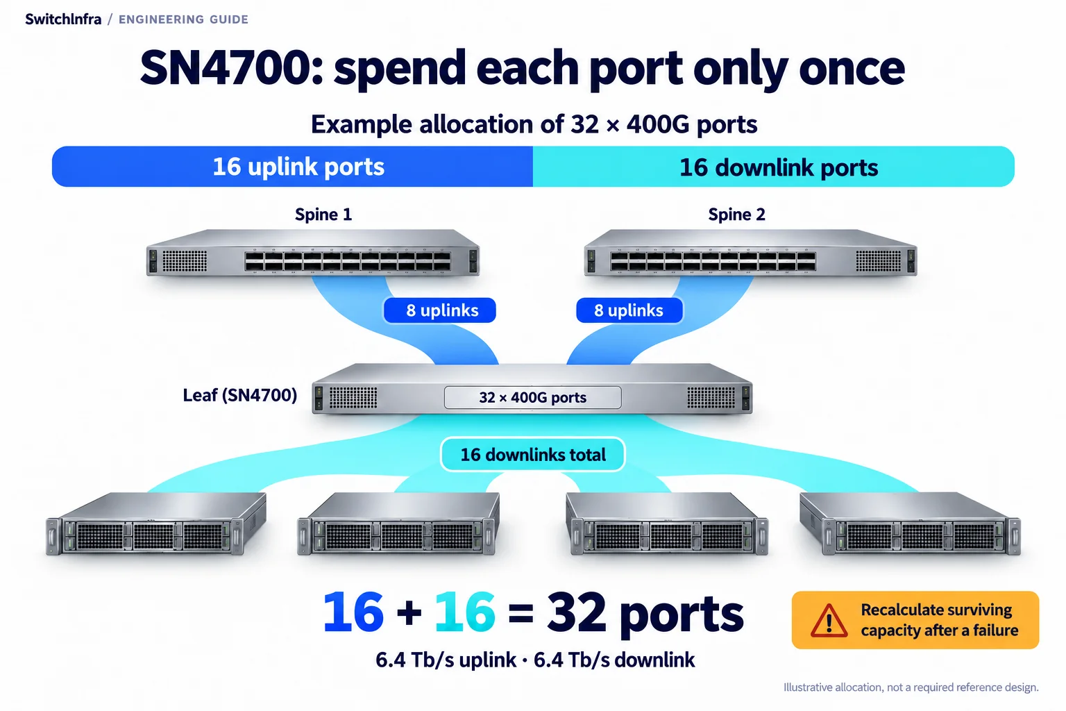
This example allocates 16 of 32 400G ports to uplinks and 16 to downlinks, giving 6.4 Tb/s in each group before failure analysis. Conceptual illustration; equipment shapes are illustrative.
Official technical sources · Independent analysis by SwitchInfra
This is a documented design analysis, not a customer deployment claim. Candidate roles require verification for your configuration.
32 — SN4700 QSFP-DD cages
400GbE — native port rate
Shared — uplink and downlink budget
Site input — acceptable oversubscription
What the technical reference establishes
NVIDIA’s SN4000 manual lists SN4700 as a Spectrum-3 platform with 32 QSFP-DD interfaces and multiple supported rate configurations. Its Layer 1 guide explains the leaf-spine connection pattern.
The useful engineering question is how many endpoint connections survive after the fabric has been connected. Start with traffic and expansion requirements, then compare a native-rate design with explicitly supported split-port alternatives.
Spectrum-3 SN4000 hardware introduction
Platform — SN4700 is listed with 32 QSFP-DD interfaces.
Rates — The hardware table includes native 400GbE operation.
Topology — A two-tier Clos connects each leaf to the spines.
Not established — A customer traffic profile or validated rack design is not supplied.
Scope of the analysis: Independent selection analysis of official NVIDIA documentation. Proposed examples are not a deployed customer project or a SwitchInfra delivery.
Work through the engineering choices
Start with the documented constraint, then state the conditions for the proposed equipment role.
Reserve the fabric connections first
The switch provides a finite set of physical interfaces.
Design exercise: Independent arithmetic example: allocate eight 400G uplinks before assigning server-facing ports.
That example leaves twenty-four native-rate cages for other duties, assuming no additional service or peer connections. Its aggregate uplink capacity is 3.2 Tb/s in one direction. The arithmetic is a planning illustration, not a recommended topology or evidence of an installed SN4700 network.
Attach each uplink to a named spine and record how the design expands. A reserve port that is needed for a later spine cannot also be promised to a server. Keep operational, future and unavailable positions visible on the same rack-facing diagram.
Spectrum-3 SN4000 hardware introduction
SN4700 family
400GbE leaf or spine candidate
32 QSFP-DD cages; exact ordering variant and software require confirmation.
Calculate bandwidth from the proposed port assignment
Supported speed options do not create simultaneous independent capacity.
Design exercise: compare aggregate server demand with the 3.2 Tb/s uplink allocation.
Total the configured downlink rates and divide by the configured uplink capacity using a consistent direction. State whether the result describes advertised port rates, expected workload demand or measured traffic. A ratio based on peak interfaces is not an application performance forecast.
If breakout is proposed, map every child port to its parent cage and confirm that the exact software and cable arrangement support the mode. Splitting changes endpoint count and rate allocation. It does not create another switch ASIC or an additional independent uplink bank.
Spectrum-3 SN4000 hardware introduction · NVIDIA Layer 1 data center guide
QSFP-DD interconnect family
SN4700 channel inquiry
Specify rate, mode, peer, media and reach before assigning a cable part.
Review the network with a component unavailable
Leaf-spine provides multiple paths when the complete design supports them.
Design exercise: Proposed acceptance question: what bandwidth remains after losing one uplink or spine?
Recalculate the ratio using surviving paths. Check whether applications tolerate the remaining throughput and recovery behavior. Avoid calling a design nonblocking merely because every individual port can operate at line rate; the fabric’s allocation and traffic pattern decide the end-to-end constraint.
Include operating-system choice, licenses, airflow direction, power supplies and rack access in the RFQ. The same broad platform name can conceal ordering differences. Ask for the exact offered model and an annotated connection schedule before comparing quotations on price alone.
NVIDIA Layer 1 data center guide · Spectrum-3 SN4000 hardware introduction
SN4600C family
100GbE comparison platform
Assess actual radix and uplink allocation rather than headline switching capacity.
Make the port map auditable
The final BOM should reconcile occupied cages, child interfaces, uplink paths and planned expansion. Each connection consumes a defined resource, even if it is not carrying traffic on delivery day.
Spectrum-3 SN4000 hardware introduction
Port allocation
Named leaf, spine and service ports with reserved positions.
Bandwidth
Configured directional rates, normal ratio and degraded-state ratio.
Configuration
Exact platform, NOS, supported breakout, interconnects and airflow.
Candidate models and selection boundaries
These are conditional model or product-family inquiries for the documented equipment roles. Confirm the required rate and complete channel before finalizing any line.
| Model / family and status | Role and condition |
|---|---|
| SN4700 family Conditional model / family inquiry | 400GbE leaf or spine candidate 32 QSFP-DD cages; exact ordering variant and software require confirmation. Spectrum-3 SN4000 hardware introduction |
| SN4600C family Conditional model / family inquiry | 100GbE comparison platform Assess actual radix and uplink allocation rather than headline switching capacity. Spectrum-3 SN4000 hardware introduction |
| QSFP-DD interconnect family Conditional model / family inquiry | SN4700 channel inquiry Specify rate, mode, peer, media and reach before assigning a cable part. Spectrum-3 SN4000 hardware introduction |
Official model or family references only. Exact SwitchInfra listings, offered configuration, supply and project compatibility have not been verified; request confirmation by model.
Continue in the relevant product family
Use the analysis to define the role before comparing catalog options.
Discuss this project
Carry the route, media, endpoint and loss requirements into the inquiry. Leave unknown quantities blank; reference port and fiber counts are not an equipment BOM.
Follow the next selection question.
Compare related decisions while keeping each source’s scope, hardware and link conditions separate.
Browse more engineering analyses →
H100 SuperPOD: four fabrics, four connection schedules
Keep compute, storage, service access and OOB management distinct before counting equipment.
Read the engineering analysisOfficial technical source
HGX Spectrum-X: separate SuperNIC and DPU duties
Keep GPU communication, converged services and management distinct in the node and fabric BOM.
Read the engineering analysisOfficial technical source
BlueField-3: include management and recovery in the BOM
Separate data ports, OOB access, RShim and server power requirements.
Read the engineering analysisOfficial technical source
Before you finalize the channel
Does 32 ports mean 32 servers plus uplinks?
No. Uplinks consume resources from the same interface budget.
Does breakout increase total switch bandwidth?
It changes interface allocation; it does not create extra aggregate capacity.
Is a calculated ratio a throughput guarantee?
No. Workload behavior, configuration and failure conditions still matter.
Can the family name determine the final cable?
No. The exact ports, mode, medium and path must be specified.
Trace the project facts and technical limits
Source check: 19 October 2026. Catalog status is stated per candidate.
Official sources read 19 October 2026. Project-specific engineering review, firmware support, exact offered parts and supply remain unconfirmed.