Network engineering
Data Center Cable Management: Build a Traceable, Serviceable Link System
Organize data-center cabling with stable link IDs, route ownership, service access and change records tied to the port map.
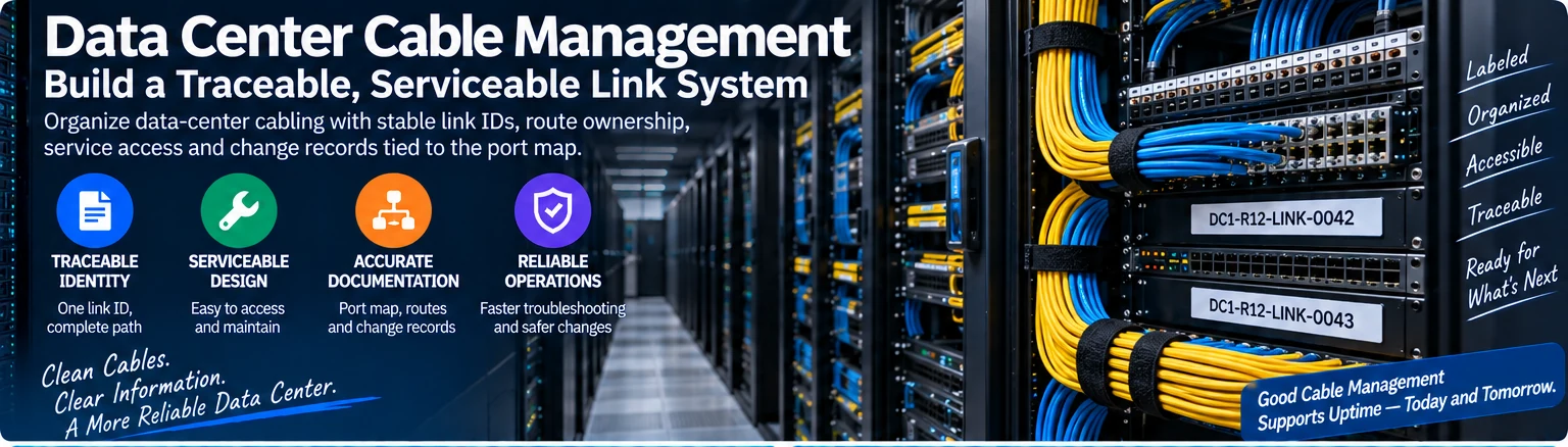
Cable management is successful when a technician can identify and service the correct path without disrupting another one. Visual neatness helps, but it is not the acceptance criterion. The design should connect physical routing, stable identifiers and change records to the network’s operational needs.
Use one identity for the complete path
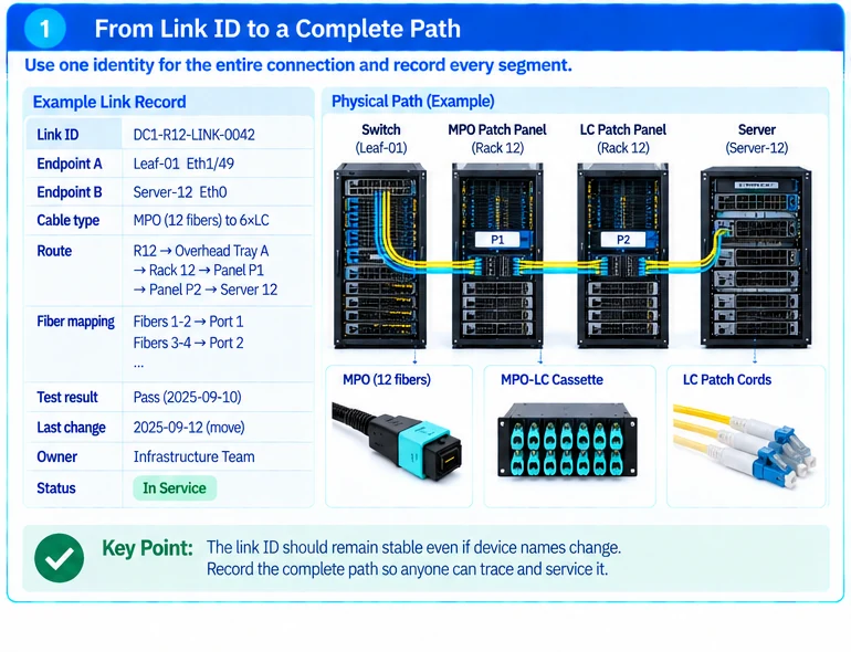
Assign each logical connection a stable link ID and map it to both endpoint ports. For a structured channel, record every intermediate panel and position. For a breakout assembly, record each branch separately while preserving the parent assembly identity.
An illustrative record might use DC1-R12-LINK-0042 as the stable identifier, with endpoint names stored in separate fields. This avoids relabeling the entire record whenever an endpoint hostname changes. The naming convention itself is a project choice; consistency and unambiguous resolution are what matter.
| Field | Purpose |
|---|---|
| Link ID | Resolves the path independently of a technician’s memory |
| Endpoint and port IDs | Identifies the active interfaces |
| Route and patch positions | Locates every serviceable segment |
| Assembly or module identifiers | Preserves supported component identity |
| Fiber mapping or branch assignment | Prevents polarity and breakout confusion |
| Test and change history | Shows what was accepted and what later changed |
Route for airflow and maintenance
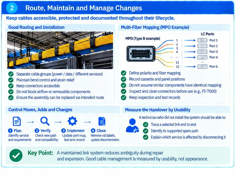
Plan separation between cable groups where required by the installation design. Preserve connector access, appropriate bend control and strain relief. Avoid using spare cable loops to occupy equipment airflow paths or block removable components.
A fixed assembly should be replaceable through its intended route. Where connectors cannot pass through a constrained pathway, resolve the installation method before purchasing the cable—not during an outage.
Make multi-fiber mapping explicit
MPO-based systems need more than a label stating fiber count. Connector arrangement, polarity and cassette mapping determine which fiber reaches which interface. Keep those properties in the channel record rather than assuming that visually similar components have identical mappings. R42
Inspection and cleaning should follow a documented process when optical connections are made or changed. An inspection record addresses connector condition; it does not by itself qualify channel loss or application reach. R17
Control moves, adds and changes
Before a change, identify the affected service and verify the proposed new path against the approved interface requirements. Afterward, update the port map and route record, retain relevant test results and remove abandoned labels or patch leads where authorized.
Do not accept a temporary patch as permanent without recording it. An undocumented workaround can remain operational for months while undermining every subsequent troubleshooting step.
Measure the handover by usability
Ask a technician who did not install the system to trace a selected link, identify its supported spare and explain which service is affected by disconnecting it. Failure of that exercise indicates a documentation or labeling gap, even when the rack looks orderly.
The deliverable is a maintained link system: as-built routing, accurate labels, usable patch schedules and an auditable change process. This reduces ambiguity during repair and expansion without making unsupported claims about guaranteed uptime.
Engineering illustrations
These figures illustrate the design concepts discussed here. They are not measured results, certified configurations or a supplied-equipment list.