Data Center Fiber Selection Worksheet: Medium, Mapping and Channel Limits
Select fiber channels by endpoint optics, active fiber count, connector arrangement, loss budget and measured installation evidence.
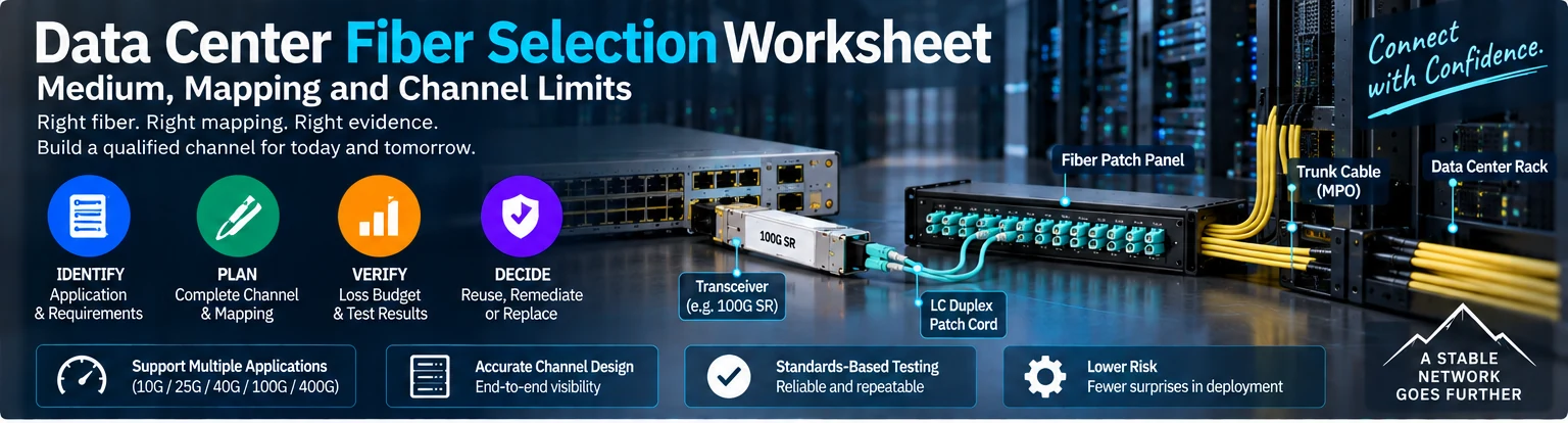
Use this worksheet when selecting a new fiber path or deciding whether an installed path can be reused. The optical application determines the channel requirement. Fiber category, connector color or nominal cable length alone is not a sufficient selection method.
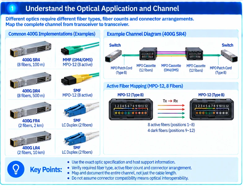
1. Identify the optical application
Record both endpoint devices, exact transceivers and target mode. Find the required fiber medium, active fiber count, connector arrangement and channel limits in the selected optical documentation. Different implementations at the same rate can require different channels. R18R25
Do not assume that a faster optic can use the existing path merely because its connector fits the panel.
2. Draw the entire channel
Include endpoint patch leads, panels, cassettes, trunks, splices and other intermediate elements. Record routed length rather than straight-line distance. For multi-fiber systems, trace the active fiber positions from transmitter to receiver. R42
| Worksheet field | Required value |
|---|---|
| Optical implementation | Exact specification and module identifiers |
| Fiber | Required medium/category and installed evidence |
| Mapping | Active fibers, polarity and cassette relationships |
| Connections | Type and count of all mated interfaces |
| Length and loss | Complete route and application-specific budget |
| Test basis | Method, reference setup, limits and result identifiers |
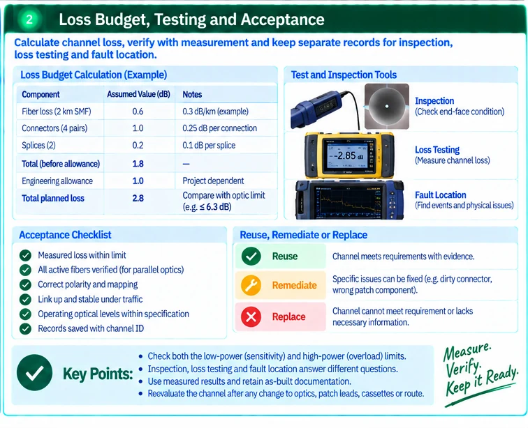
3. Calculate the planned loss
Sum justified fiber loss, connector losses, splice losses and any other passive elements. Add an explicit engineering allowance appropriate to the project. Compare the total with the selected interface’s permitted channel loss and other constraints.
An illustrative estimate of 0.6 dB fiber loss, 1.0 dB total connection loss and 0.2 dB splice loss produces 1.8 dB before allowance. The values are assumptions for arithmetic, not universal component specifications.
If a proposed extra patching stage consumes the remaining margin, reconsider the channel architecture instead of assuming that a cleaner connector will compensate indefinitely.
4. Distinguish inspection, loss and fault-location evidence
Inspection evaluates connector end-face condition. Loss testing evaluates transmission through a defined channel. Other diagnostic methods can help locate events or faults. These records answer different questions and should not be collapsed into a single unqualified pass statement. R17
For parallel optics, retain evidence for the relevant active fibers. One successful lane does not qualify the entire multi-fiber channel.
5. Decide reuse, remediation or replacement
Reuse a path when its identity and tests support the intended application. Remediate specific issues such as an unsuitable patch component or failed termination when the remaining infrastructure is appropriate. Replace when the channel cannot meet the requirement or cannot be maintained acceptably.
Keep unknown fiber identity or missing route information visible as a qualification gap. Do not infer category from color alone.
6. Preserve the accepted configuration
Link the final test report to the channel ID and as-built mapping. Reassess the affected checks after changing optics, patch leads, cassettes or route segments.
The worksheet is complete when it establishes which optical application the installed channel supports and on what evidence. This is more useful for future upgrades than a generic statement that the site uses single-mode or multimode fiber.
Engineering illustrations
These figures illustrate the design concepts discussed here. They are not measured results, certified configurations or a supplied-equipment list.