Network engineering
Modular MTP Cabling with FHD Components: Mapping, Loss and Expansion
Design an FHD-based modular fiber system by matching enclosures, cassettes, trunks, polarity and the intended optical interfaces.
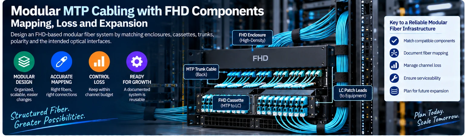
Modular fiber systems can make installation and changes more orderly, but only when their component mapping is documented. An enclosure, cassette and trunk must work as a planned channel. Matching the product-family label does not establish the optical application or the correct transmit-to-receive path.
Separate the product system from the connector
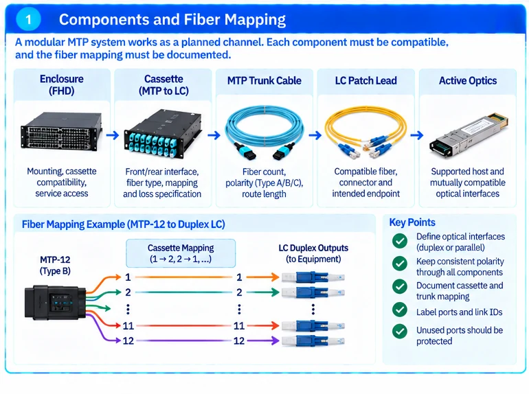
FHD refers here to FS’s modular cabling product system. It is not a universal optical interface standard. MTP is US Conec’s branded MPO connector implementation; the channel still requires compatible fiber count, mating arrangement and polarity. R39R42
Specify enclosure and cassette compatibility separately from the connector interface. Components from different mechanical systems should not be presumed interchangeable merely because they expose similar front-panel ports.
Draw the fiber mapping
Document the active optical interfaces at each end, the cassette mappings and the trunk’s fiber positions. Decide whether the channel supports duplex optical links or a parallel-optics arrangement. A passive cassette redistributes fibers; it does not turn one optical standard into another or increase the supported link rate.
| Component | Required selection data |
|---|---|
| Enclosure | Mounting, cassette compatibility and service access |
| Cassette | Front/rear interface, fiber type, mapping and loss specification |
| Trunk | Fiber count, connector arrangement, polarity and route length |
| Patch lead | Compatible fiber, connector and intended endpoint mapping |
| Active optics | Supported host and mutually compatible optical interfaces |
Budget the completed channel
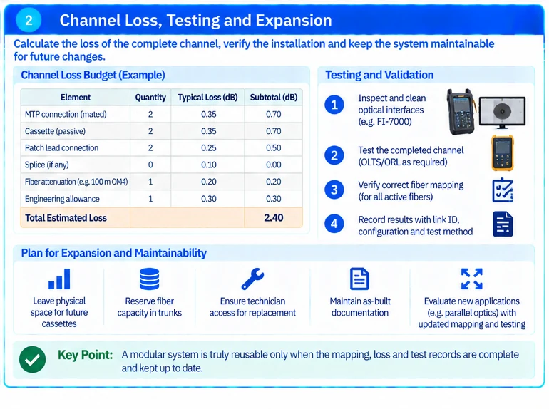
Include every mated connection and passive component in the channel-loss calculation. A high-density cassette may simplify organization while adding a connection that consumes optical margin. Use actual specified component limits and the chosen optical interface’s channel allowance.
An illustrative installation may support several duplex links through a multi-fiber trunk. Reusing that trunk for a later parallel-optics application requires a new mapping and channel review; available fibers alone do not prove that the existing cassettes are appropriate.
Reserve physical access as well as ports
Check whether technicians can release connectors, inspect interfaces and replace a cassette without disturbing neighboring live channels. Maximum catalogue port density is not always the most maintainable installed density.
Label cassette positions and link IDs consistently with the port schedule. Keep unused ports protected according to the component instructions and ensure that stored spares retain their exact configuration identity.
Test the final arrangement
Inspect and clean optical interfaces as appropriate, then test the completed mapping and relevant loss characteristics. Multi-fiber paths require evidence for the active fibers, not a single successful duplex sample. Inspection and channel testing serve different purposes and should not be conflated. R17R42
The handover should contain the enclosure/cassette/trunk BOM, polarity map, channel schedule and test results. This makes modular cabling genuinely reusable: future changes can be evaluated against a known system instead of a collection of visually similar components.
Engineering illustrations
These figures illustrate the design concepts discussed here. They are not measured results, certified configurations or a supplied-equipment list.