Network engineering
Industrial Ethernet Ring Design: Recovery Without Hidden Failure Assumptions
Design industrial Ethernet rings with explicit protection domains, protocol interoperability, environmental requirements and controlled fault tests.
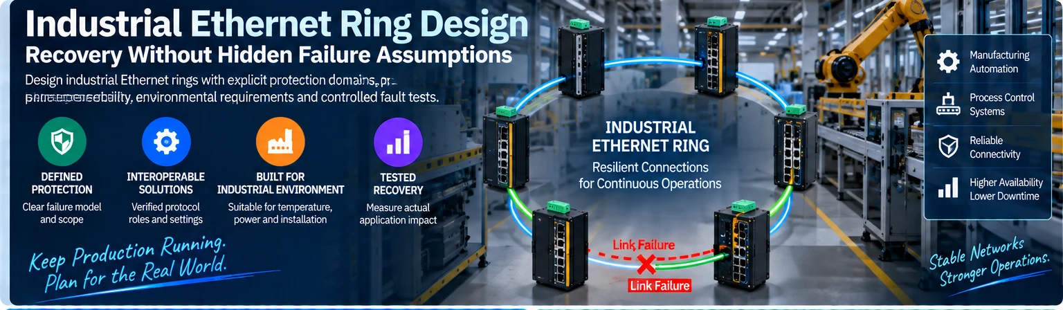
An industrial ring can provide an alternate communication path after a defined network fault. It does not automatically protect every device, power source or application. The design must state the protection domain and verify how network recovery affects the actual industrial service.
Define the protected failure
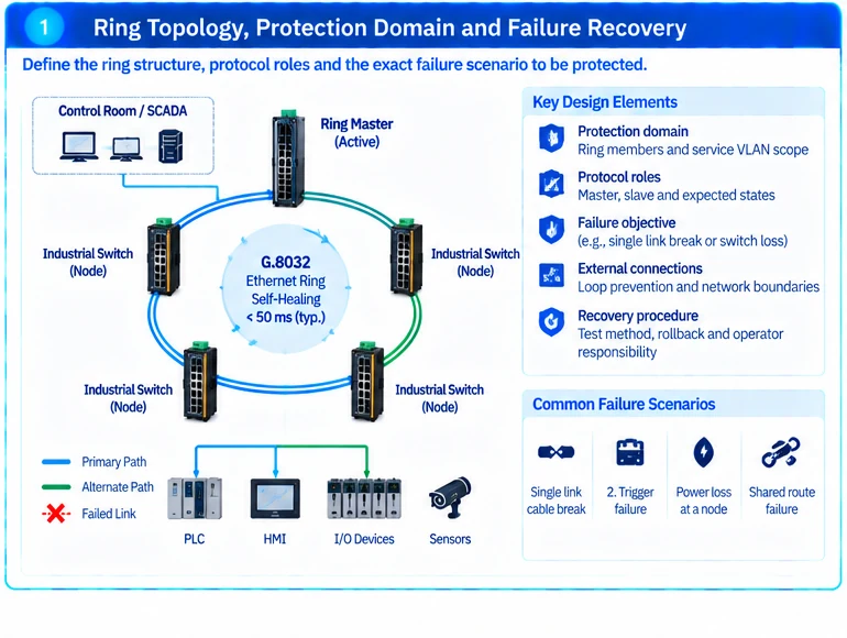
Draw the ring nodes, access devices and any connections to other networks. Identify which links share routes or power sources. State whether the requirement concerns one cable break, one switch loss or another specific event.
A single-connected endpoint still depends on its local attachment even when the backbone is a ring. Likewise, two ring directions sharing the same physical pathway may not provide the intended cable-failure resilience.
Select and configure one reviewed protection design
ITU-T G.8032 defines Ethernet ring protection switching. The presence of a related feature name on several devices is not proof that their exact implementations and settings will interoperate in the proposed topology. Confirm supported versions, roles and limits against the equipment documentation. R38
| Design record | Required content |
|---|---|
| Protection domain | Ring members, protected links and service VLAN scope |
| Protocol roles | Configured control roles and expected blocked/forwarding state |
| External connections | Loop prevention and interaction with other network domains |
| Failure objective | Event, expected network response and application tolerance |
| Recovery procedure | Test method, rollback and responsible operators |
Avoid mixing protection mechanisms without understanding their interaction. An apparently redundant connection can introduce a loop if it lies outside the assumed control domain.
Match equipment to the installation
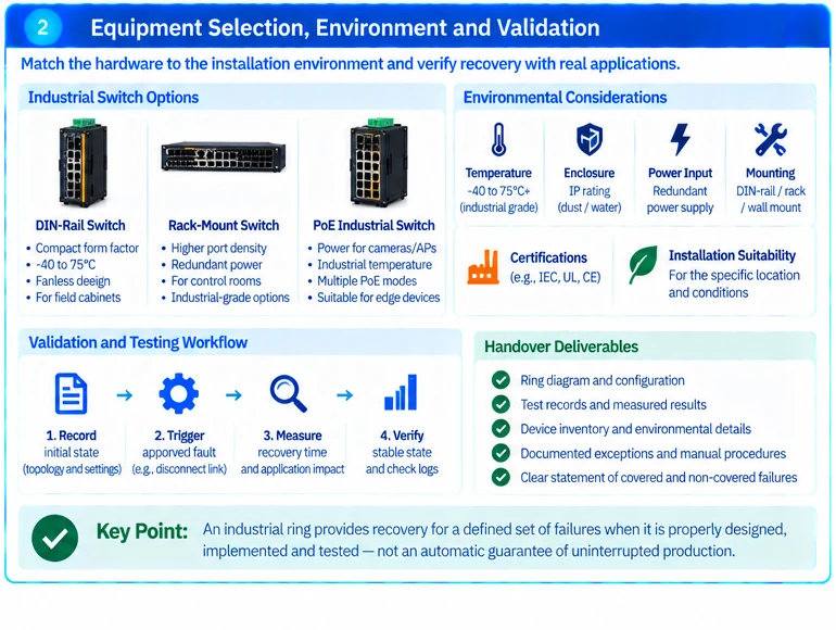
Verify temperature, enclosure, mounting, power and environmental requirements for each location. A rack switch used in an equipment room should not automatically be specified for an exposed production cabinet. Required certifications and installation suitability must be established for the exact equipment and project.
Operational technology also has availability and safety constraints that affect maintenance and testing. Coordinate with the process owner rather than applying ordinary office-network change practices. R34
Measure application recovery separately
Protocol convergence time is only one part of the outcome. Address resolution, sessions, application retry behavior and endpoint dependencies may extend the service interruption. Do not promise a particular end-to-end recovery time solely from a ring-protection feature.
In an illustrative acceptance sequence, capture normal topology state, trigger an approved single-link fault, observe forwarding changes and measure the affected application transaction. Restore the link and verify the intended stable state. Perform additional fault cases only when they are part of the approved test scope.
Hand over the failure model
Retain the ring diagram, protocol settings, environmental qualification, test records and exceptions. Operators should know which failures are protected and which still require a manual recovery action.
The resulting design is a documented protection mechanism for a defined industrial service. It is not a blanket claim of uninterrupted production or a substitute for safety-system engineering.
Engineering illustrations
These figures illustrate the design concepts discussed here. They are not measured results, certified configurations or a supplied-equipment list.