Network engineering
Building Backbone Cabling: Capacity, Route Resilience and Service Access
Plan building backbone fiber around telecommunications rooms, service growth, pathway diversity and channel-level acceptance.
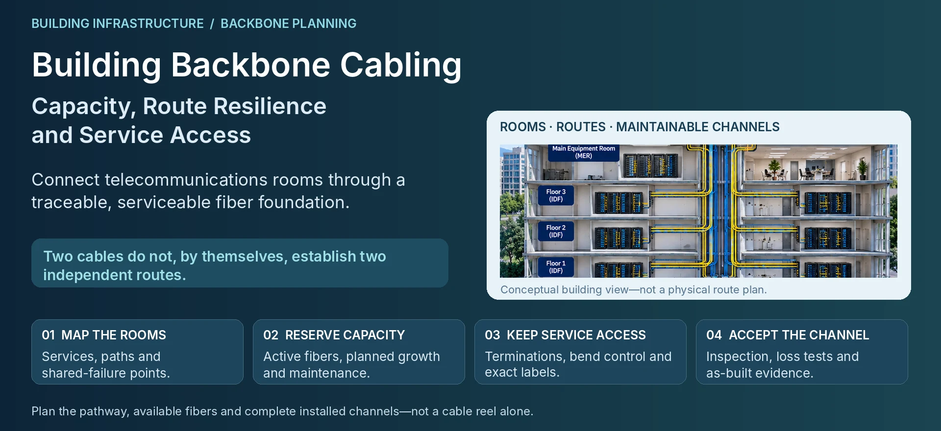
A building backbone connects telecommunications rooms to the services that access networks depend on. It should be designed as a maintained pathway with capacity and failure objectives, not merely as a cable pulled through a riser. The decisions made during installation influence later network upgrades and restoration work.
Map rooms, services and physical routes
Identify the main equipment room, floor distribution rooms and the services each must reach. Record routed lengths, pathway access, existing congestion and restrictions on installation work. Include building-management and safety requirements through the appropriate qualified project teams.
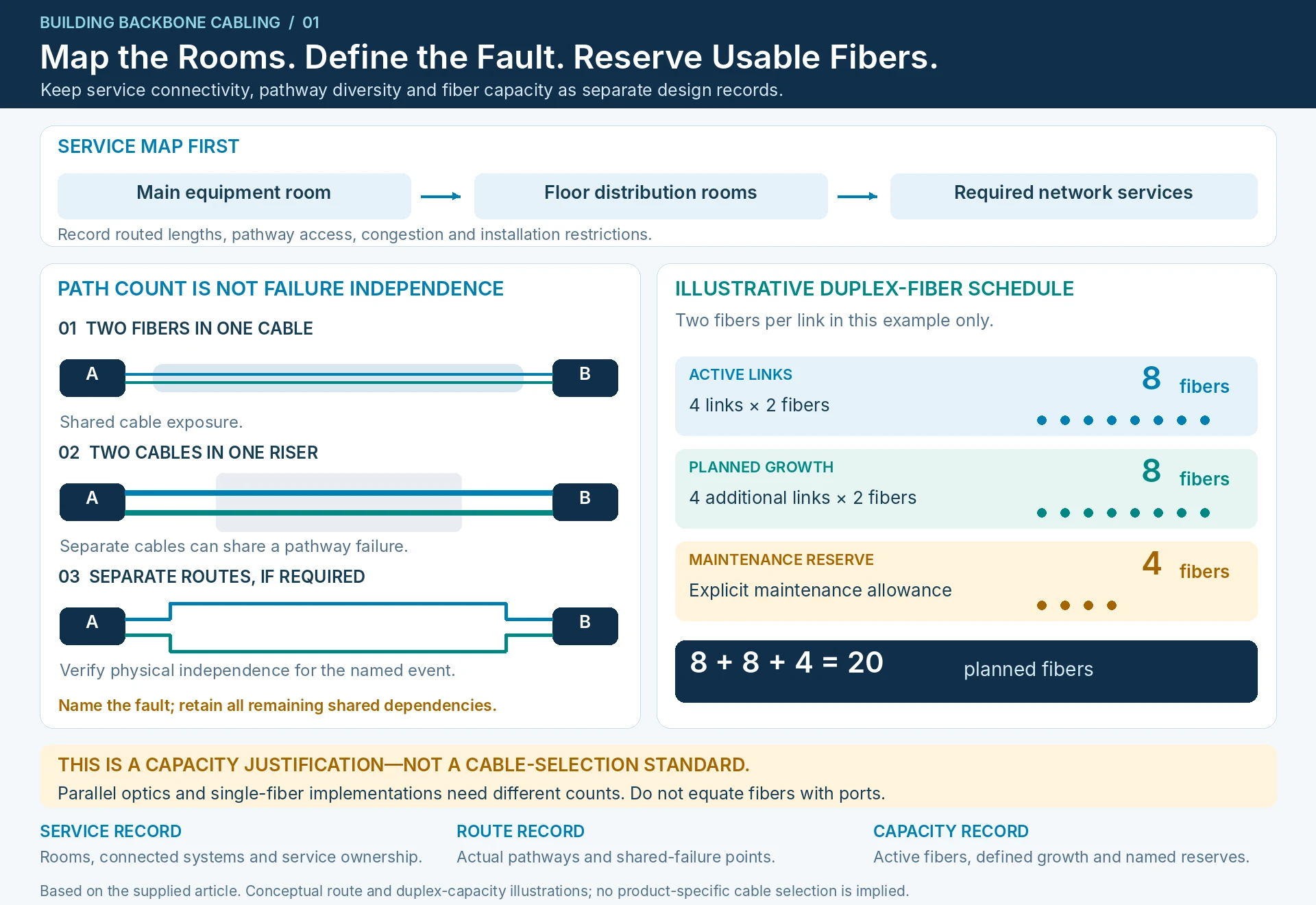
Separate network redundancy from pathway diversity. Two fibers in the same cable share many physical risks. Two cables in the same riser may also share a failure. State which events the proposed arrangement is intended to tolerate.
Reserve usable capacity
Count fibers from the planned optical interfaces and link arrangement, then add explicit growth and maintenance allowances. Do not equate fiber count with port count without considering the selected optical implementation.
For an illustrative duplex-fiber design, four active links require eight fibers. Four additional planned links require another eight, and a four-fiber maintenance reserve brings the total to twenty. This arithmetic is not a cable-selection standard; it explains why the project needs its chosen capacity. A parallel-optics or single-fiber design requires a different calculation.
| Record | What it should show |
|---|---|
| Service map | Rooms and systems connected by each backbone path |
| Capacity schedule | Active fibers, planned growth and named reserves |
| Route drawing | Actual pathway and shared-failure points |
| Termination plan | Panels, connector arrangement, polarity and labeling |
| Acceptance record | Inspection, test method, results and as-built identifiers |
Select a complete channel arrangement
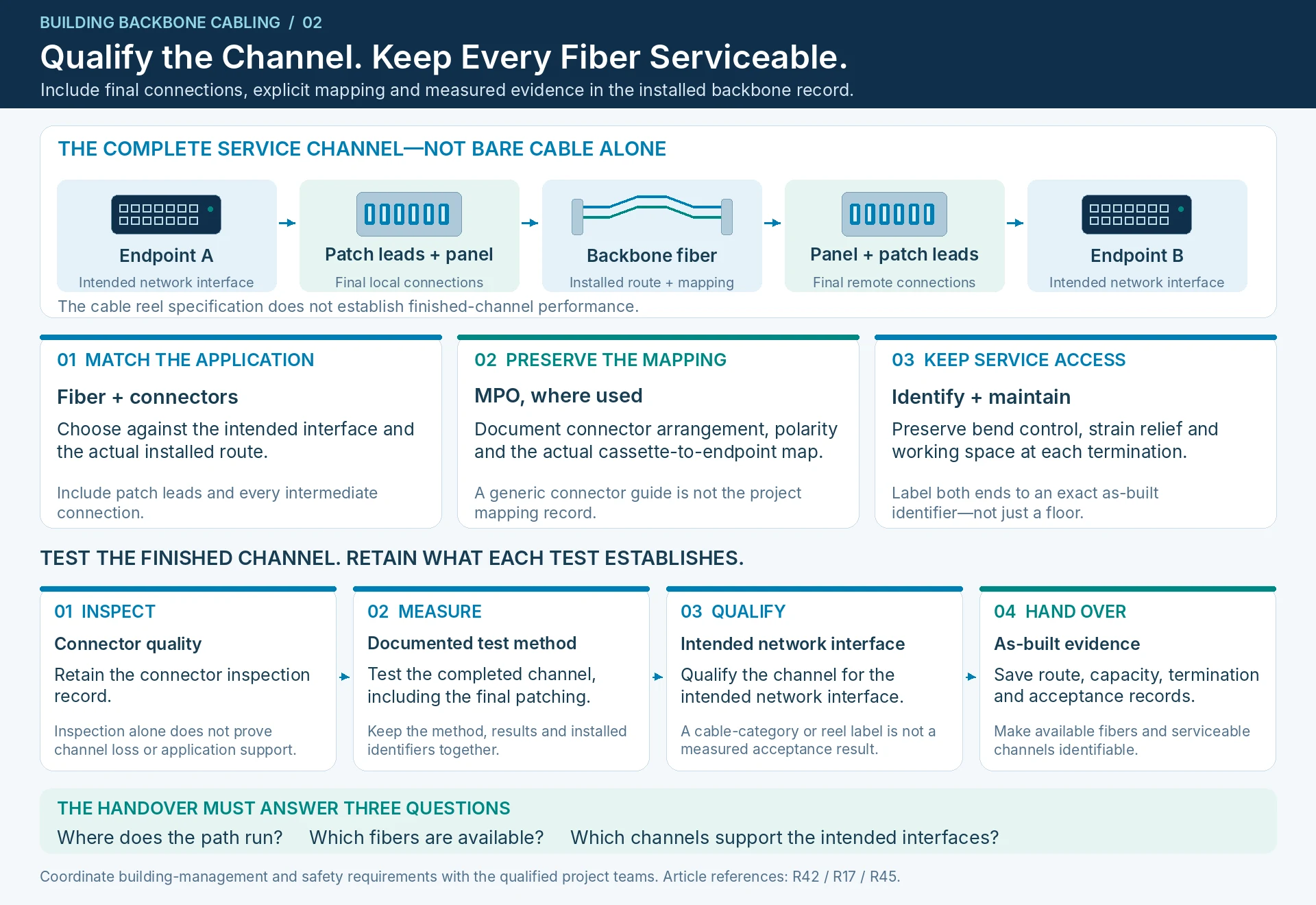
Choose fiber and connectors against the intended applications and installed route. Include patch leads and intermediate connections in the channel design. A cable reel specification does not establish the performance of the finished installation.
Where multi-fiber connectors are used, polarity and mapping must be explicit. MPO-related guidance is useful for identifying these connection-management issues, but the project’s actual cassette and endpoint arrangement still needs its own record. R42
Design for access after handover
Place terminations where technicians can identify and service them without disturbing unrelated links. Preserve bend control, strain relief and working space. Label both ends using an identifier that resolves to the as-built schedule; labels that name only a floor are insufficient when several services share a route.
Inspect and test the completed channel using an appropriate documented method. Fiber inspection supports connector quality checks, but it does not replace the required loss or application qualification. R17
The backbone handover should allow a future engineer to answer three questions without reopening the design: where the path runs, which fibers are available, and which installed channels support the intended network interfaces. Campus architecture can then evolve on top of a traceable physical foundation. R45
Engineering illustrations
These figures illustrate the design concepts discussed here. They are not measured results, certified configurations or a supplied-equipment list.