
Campus networks
How should a 24-fiber MTP trunk serve 40G and eight 10G links?
Map custom cassettes before selecting native 40G, duplex 10G or an independently proposed breakout design.
A university cabling account offers a useful allocation problem: eight fibers for a 40G inter-switch connection and sixteen for eight 10G links. The selection starts at the custom cassette—not the switch’s headline speed.
The short answer
Map every fiber through both cassettes before choosing optics. Evaluate parallel 40G SR4 only on a verified multimode path; treat the eight duplex 10G links and optional QSFP breakout as separate designs.
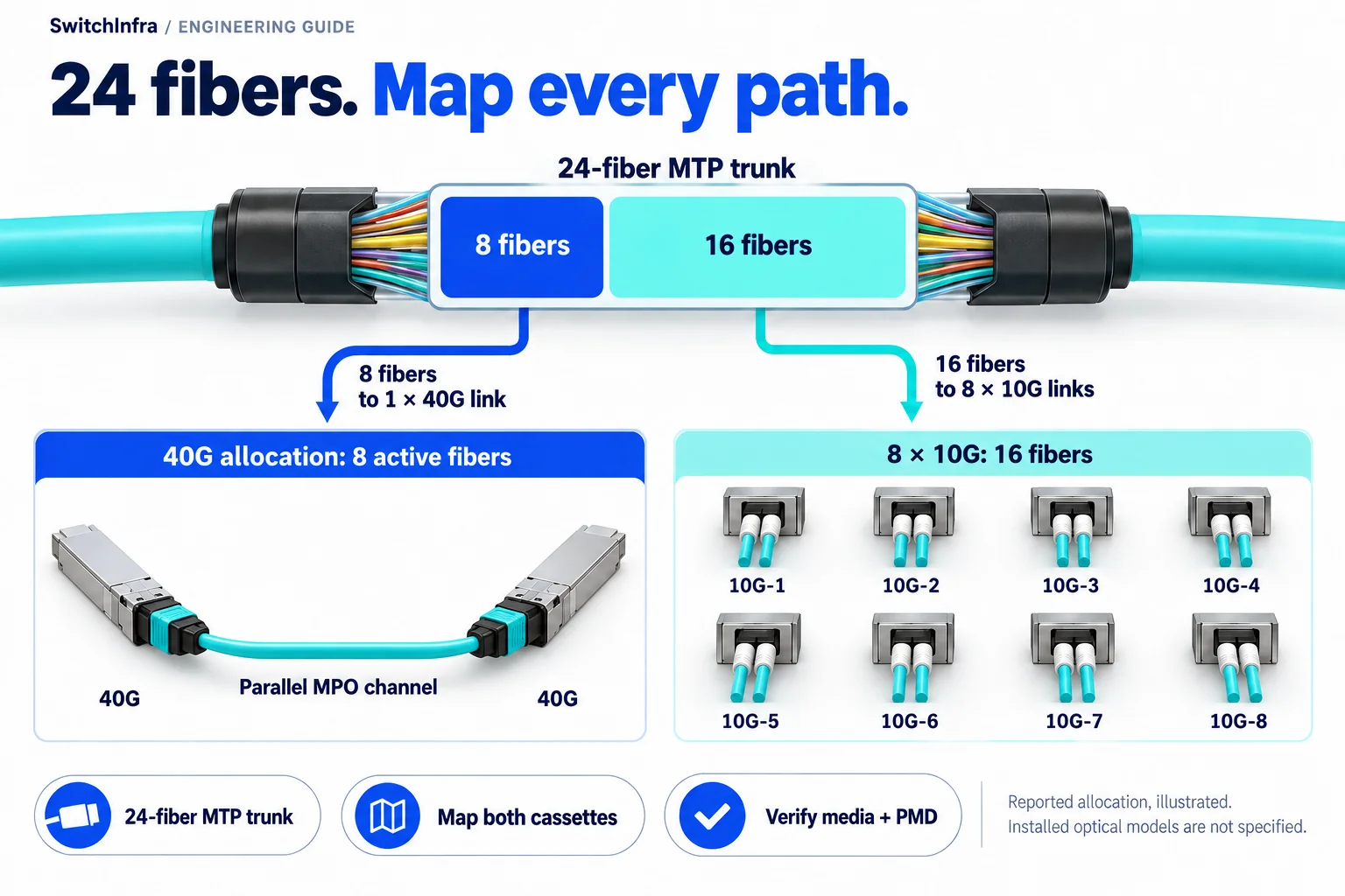
A reported 24-fiber allocation reserves eight fibers for one 40G channel and sixteen for eight duplex 10G links. The cassette mapping determines the usable paths. Conceptual illustration; equipment shapes are illustrative.
Third-party project account · Independent analysis by SwitchInfra
Not a SwitchInfra deployment. Candidate equipment is proposed for comparable requirements.
24 — fibers in the reported MTP system
8 — fibers allocated to 40G
8 × 10G — links using sixteen fibers
Unknown — installed optics and PMDs
What the documented project tells us
Leviton describes preterminated cabling and custom cassettes at Johnson C. Smith University’s Science Center. Its account also lists single-mode fiber separately, without identifying the media or optical PMD of the 40G connection.
That distinction matters when preparing a comparable BOM. A fiber count can balance perfectly while the equipment-facing connector, lane mapping or optical standard remains wrong.
Trunk — A 24-fiber MTP system is reported.
Allocation — Eight fibers serve 40G; sixteen serve eight 10G links.
Termination — The account describes custom cassettes.
Not disclosed — Optic models, PMDs, distances and measured loss are unknown.
Scope of the analysis: This is an independent selection example based on a manufacturer’s project account, not a reconstruction of installed equipment or a SwitchInfra deployment.
Work through the engineering choices
Start with the documented constraint, then state the conditions for the proposed equipment role.
Map the 24 fibers to actual equipment ports
The published design divides the trunk between 40G and 10G roles.
Design exercise: produce a port-to-port fiber schedule for a comparable installation.
Label both trunk ends, cassette ports and individual fiber positions. Verify continuity, polarity and the routing through each assembly; record which positions reach each equipment port.
A 24-fiber MTP termination is not automatically an MPO-12 SR4 interface. Specify the cassette or fanout that provides the required mapping. Unused positions at one connector do not necessarily become usable ports elsewhere.
Evaluate a native 40G path
Eight fibers are assigned to the inter-switch connection.
Design exercise: a multimode 40GBASE-SR4 channel.
SR4 uses four transmit and four receive fibers. This makes it a candidate architecture to investigate, but does not identify the original installation. Confirm multimode grade, the complete channel loss and MPO-12 mating arrangement before selecting it.
QSFP-40G-SR4-S supports native 40G, not 4 × 10G breakout. QSFP-40G-SR4 can support breakout with an appropriate host and channel. For either SR4 path, the reference reach is 100 m on OM3 or 150 m on OM4; actual loss may constrain it further.
QSFP-40G-SR4-S
Native 40G multimode candidate
No 4 × 10G breakout; model inquiry only.
QSFP-40G-SR4
Native 40G or conditional breakout
Verify host mode and fiber mapping; model inquiry only.
Keep duplex 10G separate from QSFP breakout
The account assigns sixteen fibers to eight 10G links.
Design exercise: eight independent duplex multimode links.
Each duplex link needs a transmit/receive pair presented to the correct endpoint ports. SFP-10G-SR is a candidate for verified multimode channels, with duplex LC interfaces and suitable hosts. It is not a single-mode optic.
Eight duplex links do not prove that two QSFP ports operate in breakout mode. If breakout is proposed independently, verify software, lane ordering and compatible SR endpoints. Keep the SR4 channel’s 100/150 m limits; do not substitute standalone 10G SR’s longer reach.
SFP-10G-SR
Duplex multimode 10G candidate
Verify media, host and complete channel; model inquiry only.
Make the cassette map part of the RFQ
Quote the channel as well as the optics. A connector name alone cannot establish compatibility.
Mapping
Cassette/fanout part numbers, fiber positions, polarity and equipment-facing connectors.
Optical channel
Media grade, routed length, measured loss, connector finish and test results.
Host configuration
Both switch models, software, port mode, native 40G versus breakout, and quantities.
Candidate models and selection boundaries
These are illustrative model inquiries, not the equipment installed in the source project. Confirm the required rate and complete channel before finalizing any line.
| Model / family and status | Role and condition |
|---|---|
| QSFP-40G-SR4-S Conditional model inquiry | Native 40G on verified MMF MPO-12; excludes 4 × 10G breakout. Cisco 40G optics |
| QSFP-40G-SR4 Conditional model inquiry | 40G or host-supported breakout Confirm channel mapping and OM3/OM4 reach. Cisco 40G optics |
| SFP-10G-SR Conditional model inquiry | Duplex 10G on verified MMF LC interface; not for a single-mode channel. Cisco 10G optics |
Linked product IDs identify verified catalog listings. Unlinked entries remain model or family inquiries; their listings have not been verified. Availability, unit condition and platform compatibility need confirmation for every line.
Continue in the relevant product family
Use the analysis to define the role before comparing catalog options.
Network Modules and Line Cards
Discuss this project
Carry the route, media, endpoint and loss requirements into the inquiry. Leave unknown quantities blank; source-project fiber counts are not an equipment BOM.
Follow the next selection question.
Compare related decisions while keeping each source’s scope, hardware and link conditions separate.
Browse more engineering analyses →
Campus OS2: qualify both routes before choosing optics
Use Newcastle’s Catalyst Building account to examine per-route channel budgets and protection requirements. The installed link rates remain undisclosed.
Read the engineering analysis · Original project account
Single-mode university data center: 100G / 40G selection
A G.657.A2 fiber plant makes the complete optical channel central to the equipment choice.
Read the engineering analysis · Original project account
Expand mixed OM4 and single-mode cabling
A public Xi’an expansion account becomes a practical guide to channel allocation, 1U fiber density and patching-loss budgets.
Read the engineering analysis · Original project account
Before you finalize the channel
Does MTP mean multimode?
No. It identifies a connector system. Check the actual fiber grade and optical standard.
Does eight fibers for 40G prove SR4?
No. It suggests an architecture to investigate; the case does not disclose its PMD.
Are SR4-S and SR4 interchangeable for breakout?
No. SR4-S lacks 4 × 10G support. Non-S SR4 still needs a supported host configuration.
Can these models be ordered from SwitchInfra?
Targeted catalog checks found no exact listings. Request model-based supply and compatibility confirmation.
Trace the project facts and technical limits
Source check: 19 October 2026. Catalog status is stated per candidate.
Sources and catalog checked 19 October 2026. Source publication date is unverified. Installed optics, current configuration, supply and platform-specific compatibility remain unconfirmed.