
Data centers
How should a live data center expand mixed OM4 and single-mode cabling?
A public Xi'an expansion account becomes a practical guide to channel allocation, 1U fiber density and patching-loss budgets.
An expansion with two fiber media demands a channel-by-channel plan. Start with usable connections and measured loss before converting rack density into an optical BOM.
The short answer
Separate OM4 and single-mode channels, count complete usable paths, and include every cassette and patch connection in the loss budget. Choose optics against those paths.
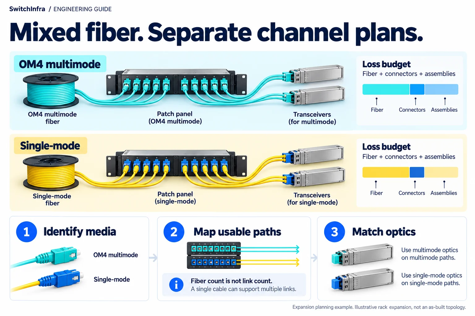
Plan OM4 and single-mode channels separately, including endpoint optics, patching and the complete loss budget. Conceptual illustration; equipment shapes are illustrative.
Third-party project account · Independent analysis by SwitchInfra
Not a SwitchInfra deployment. Candidate equipment is proposed for comparable requirements.
OM4 + SMF — Supplier-reported trunk media
10,000+ — Additional points reported
1U / 144 fibers — Stated distribution density
Undisclosed — Actual link speeds and optics
What the documented project tells us
Adding fiber inside an operating data center creates a practical purchasing problem: a dense panel can offer plenty of terminations while leaving too few complete channels for the next server row.
This public project analysis uses a supplier account to examine that problem. The selection examples below are independent engineering options; they do not identify equipment installed at Xi’an.
iCONEC: State Grid Xi’an data-center expansion
Expansion — iCONEC reports more than 10,000 additional points in the phase-three expansion.
Fiber media — The account lists OM4 multimode and G657A2 single-mode pre-terminated MTP trunks.
Distribution — EDA–MDA connections use its high-density UDF distribution system.
Panel arrangement — The stated specification is 1U, 144 fibers, with LC adapters.
Scope of the analysis: Third-party supplier account. Not a SwitchInfra deployment. No link schedule, switch inventory, actual speeds or measured loss report is disclosed.
Work through the engineering choices
Start with the documented constraint, then state the conditions for the proposed equipment role.
Keep each fiber medium identifiable end to end
The source names both OM4 and G657A2 trunks.
Design exercise: a new 10G connection; its actual rate is a project input.
Record the media at both equipment ports, every trunk, cassette and jumper. An LC faceplate does not reveal whether the underlying channel is multimode or single-mode.
For a hypothetical duplex 10G channel, SFP-10G-SR is an OM4 candidate; SFP-10G-LR is a single-mode candidate after checking the installed fiber. Neither is an interchangeable choice based solely on connector shape.
Cisco 10G optical module specifications
SFP-10G-SR
Hypothetical 10G OM4 channel
Model inquiry; host, channel and supply unverified.
SFP-10G-LR
Hypothetical 10G single-mode channel
Model inquiry; verify installed fiber, host and channel.
Translate fiber density into complete usable paths
The supplier states 144-fiber density in 1U.
Design exercise: Counting example: 144 available fibers ÷ two fibers per duplex pair = 72 pairs at that panel.
That arithmetic does not establish 72 working links. Count only pairs with continuous, correctly mapped paths to the far end, available adapters and matching equipment ports. Reserve spare and protected capacity explicitly.
A cassette may convert a multifiber trunk into duplex LC interfaces. Request its actual fiber map and polarity; MTP does not prove a parallel optical PMD. Build the BOM from channel assignments, not the panel’s headline density.
CommScope cassette and distribution reference
Budget the whole channel before reconnecting service
The account describes pre-terminated trunks and dense distribution.
Design exercise: Expansion example: an extra cross-connect adds connection loss without adding useful reach.
Include trunk attenuation, cassette assemblies, mated connections and any splices. Use assembly specifications consistently so connector loss is not counted twice. Confirm the resulting channel against the exact optical module’s limit.
For the 10G examples, Cisco lists up to 400 m on OM4 for SR and up to 10 km on specified single-mode fiber for LR. Those are reference reaches, not permission to ignore channel loss, minimum distance or host support.
Cisco 10G optical specifications and limits · Cisco optics compatibility matrix
Specify a migration package, not just optical modules
Ask for a labeled channel schedule, the intended outage sequence and acceptance records. Keep the existing service path identified until the replacement has passed its agreed checks. A successful optical link is only one part of a usable migration.
Browse optical transceiver families · Cisco optics compatibility matrix
Path
Media, termination, cassette mapping, polarity, distance and occupied capacity.
Equipment
Both host models, software, port modes and exact optical PIDs.
Acceptance
Connector inspection, channel test results and agreed service checks before handover.
Candidate models and selection boundaries
These are illustrative model inquiries, not the equipment installed in the source project. Confirm the required rate and complete channel before finalizing any line.
| Model / family and status | Role and condition |
|---|---|
| SFP-10G-SR Conditional model inquiry | 10G OM4 example Duplex LC, 850 nm. Confirm complete channel and host support. Cisco 10G data sheet |
| SFP-10G-LR Conditional model inquiry | 10G single-mode example Duplex LC, 1310 nm. Verify installed fiber and optical limits. Cisco 10G data sheet |
Linked product IDs identify verified catalog listings. Unlinked entries remain model or family inquiries; their listings have not been verified. Availability, unit condition and platform compatibility need confirmation for every line.
Continue in the relevant product family
Use the analysis to define the role before comparing catalog options.
Discuss this project
Carry the route, media, endpoint and loss requirements into the inquiry. Leave unknown quantities blank; source-project fiber counts are not an equipment BOM.
Follow the next selection question.
Compare related decisions while keeping each source’s scope, hardware and link conditions separate.
Browse more engineering analyses →
Single-mode university data center: 100G / 40G selection
A G.657.A2 fiber plant makes the complete optical channel central to the equipment choice.
Read the engineering analysis · Original project account
24-fiber MTP: one allocation, different optical choices
Map custom cassettes before selecting native 40G, duplex 10G or an independently proposed breakout design.
Read the engineering analysis · Original project account
Campus OS2: qualify both routes before choosing optics
Use Newcastle’s Catalyst Building account to examine per-route channel budgets and protection requirements. The installed link rates remain undisclosed.
Read the engineering analysis · Original project account
Before you finalize the channel
Does 144-fiber density mean 144 equipment ports?
No. Duplex channels typically consume two fibers. Available channels also depend on the far-end path, cassettes, adapters, reservations and equipment ports.
Can SR and LR connect across the same LC patch panel?
An LC interface alone is insufficient. Match the complete channel’s fiber medium and optical PMD at both ends.
Does the source prove a 100G upgrade?
No actual link rate is disclosed. A future 100G design needs its own host, PMD, media and loss review.
What should an RFQ include?
Send link quantities, media and cassette maps, distances, test results, both host configurations and the migration window. These models are inquiries, with availability unconfirmed.
Trace the project facts and technical limits
- iCONEC: State Grid Xi’an data-center expansion
- Cisco 10G optical module specifications
- CommScope cassette and distribution reference
- Cisco optics compatibility matrix
- Browse optical transceiver families
Source check: 19 October 2026. Catalog status is stated per candidate.
Source and specification check: 19 October 2026. Platform-specific engineering review remains open. Targeted catalog searches found no exact listing for these two optical PIDs.