Network engineering
DWDM-PAM4 DCI Design: Qualify the Optical System, Not Just the Pluggable
Plan DWDM-PAM4 data-center interconnects with wavelength assignment, line-system requirements, channel limits and end-to-end ownership.
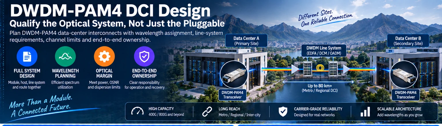
DWDM-PAM4 can describe a particular optical implementation for carrying data-center traffic over a wavelength-multiplexed route. It is not a guarantee that a pluggable module can be inserted into any switch and connected directly across any long fiber. The module, host interface and optical line system must be qualified together.
Separate the terminology
DWDM concerns the use of multiple optical wavelengths. PAM4 describes a signaling approach. Neither term, by itself, establishes the full transmission system or makes a product equivalent to a coherent interface. Start with the exact module documentation and the supported application.
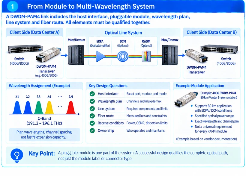
A concrete example of why this matters is a vendor DWDM-PAM4 product whose stated 80 km application includes EDFA/DCM conditions. That is a condition of that product’s implementation, not a universal requirement or capability of every PAM4 module. R41
Describe the full optical path
Draw both client endpoints and every line-system element between them. Record wavelength assignments, multiplexing components, fiber route, amplification or compensation where required, monitoring points and responsible operators.
| Design question | What must be resolved |
|---|---|
| Host interface | Exact supported port, module and operating mode |
| Wavelength plan | Matched channels and compatible mux/demux arrangement |
| Line system | Required active/passive components and their operating limits |
| Fiber route | Measured loss and other applicable transmission constraints |
| Receive conditions | Permitted operating range at every relevant interface |
| Ownership | Who commissions, monitors and restores each segment |
A rate label and LC connector do not answer these questions. Nor does a successful power reading prove every transmission requirement has been met.
Design margin across the system
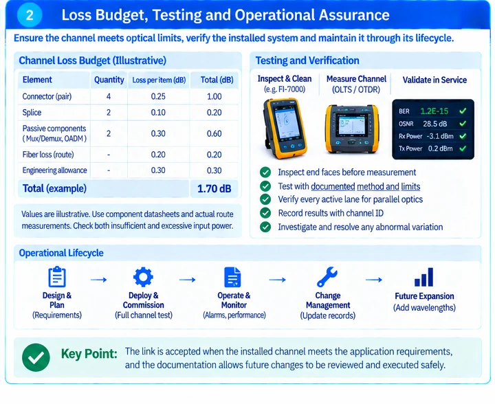
Use component specifications and measured route information to determine the supported operating envelope. Include connector and splice losses, passive-component losses and the limits introduced by the selected line system. Evaluate both insufficient power and excessive input power where applicable.
Do not prescribe amplification or attenuation without a system calculation. Adding optical power can create a different problem, while an attenuator does not correct an unsupported wavelength or dispersion condition. Long-reach transceiver documentation illustrates why individual optical variants have different limits. R18
Commission one complete channel before expanding wavelengths
Validate the host interfaces and the full optical route with the intended configuration. Record operating levels, relevant diagnostics, error behavior and traffic-test conditions. Then confirm the behavior of the planned populated wavelength configuration rather than assuming that one isolated channel proves every loading condition.
Coordinate maintenance and escalation across the network and optical teams. A switch operator must know whether an alarm belongs to the local module, a passive route or a managed line system.
The deliverable is a qualified DCI system and a responsibility map. A sourcing request should therefore include endpoint models, required capacity, wavelength plan, route measurements and any existing transport equipment. Requesting only “80 km DWDM modules” leaves the essential engineering work unfinished.
Engineering illustrations
These figures illustrate the design concepts discussed here. They are not measured results, certified configurations or a supplied-equipment list.