
SFP-10G-ZR Qualification: Check Both Loss Margin and Receiver Overload
Qualify SFP-10G-ZR links with exact variant support, worst-case power calculations, dispersion conditions and measured channel evidence.
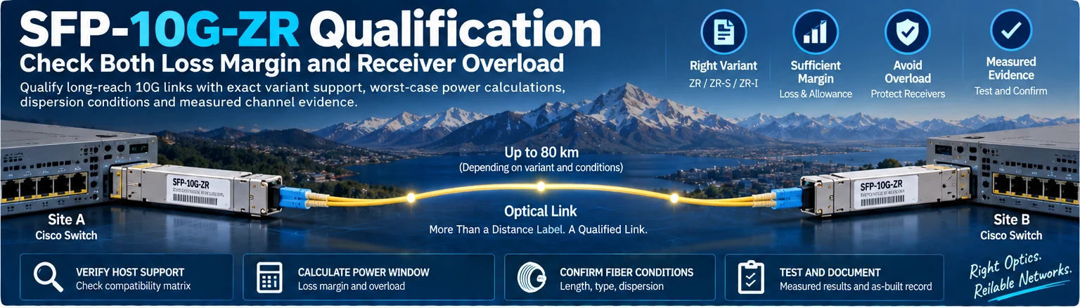
Use this guide to review a proposed SFP-10G-ZR connection before installation. It covers host support, optical-budget checks and evidence required for acceptance. The exact suffix and operating mode matter; specifications for one ZR variant should not be transferred to another without checking the manufacturer documentation.
1. Confirm the exact variant and host
Record both transceiver identifiers, host ports and software baselines. Verify host support independently at each end. A module’s reach specification does not establish that a particular host supports it. R49
Cisco’s data sheet distinguishes SFP-10G-ZR, ZR-S and ZR-I and their operating conditions. It also describes the ZR interface as a Cisco specification rather than part of the original 10 Gigabit Ethernet standard. R18
2. Calculate the low-power boundary
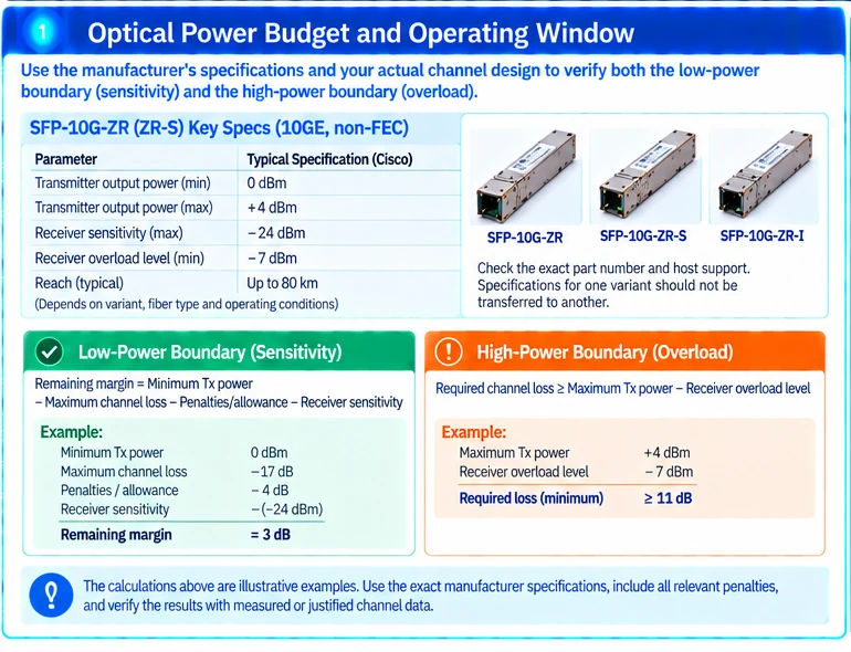
For the documented SFP-10G-ZR/ZR-S 10GE non-FEC conditions, Cisco lists minimum transmit power of 0 dBm and receiver sensitivity of −24 dBm. Their difference is a 24 dB sensitivity-based budget before relevant penalties and engineering allowances. R18
Use:
remaining margin = minimum Tx power − maximum channel loss − required penalties/allowance − receiver sensitivity
For an illustrative channel with 17 dB maximum loss and 4 dB combined planned penalties/allowance, the calculation is 0 − 17 − 4 − (−24) = 3 dB. This is not a qualified route; every assumption still needs evidence.
3. Check the high-power boundary separately
The same documented variant has a maximum transmitter output of +4 dBm and receiver overload level of −7 dBm under the stated conditions. The receiver damage threshold is a different limit; operating below damage does not mean operating within specification. R18
A simplified power-window calculation therefore requires at least 11 dB of loss between those worst-case values to avoid exceeding −7 dBm. Do not use that arithmetic as a substitute for the manufacturer’s attenuation guidance and full channel review.
4. Include the constraints that power arithmetic misses
| Check | Evidence |
|---|---|
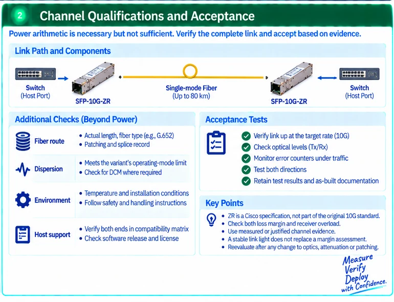
| Fiber route | Actual length, fiber type and patching/splice record |
| Loss | Measured or justified worst-case channel loss |
| Dispersion | Compliance with the exact variant and operating-mode limit |
| Attenuation | Manufacturer guidance plus the actual transmitter/receiver calculation |
| Environment | Relevant temperature and installation conditions |
Do not directly patch long-reach optics for convenience without resolving overload protection. Follow the equipment safety and installation instructions and use qualified personnel.
5. Accept the installed channel
Retain inspection and channel-test results, operating optical levels where available, module identity and relevant error observations under traffic. Check both directions. A stable link light does not replace an error or margin assessment.
Configure monitoring using the applicable documented limits and preserve the as-built route. Reevaluate the channel after changes to optics, attenuation or patching.
The completed record should show an acceptable operating window with justified margin, not simply an “80 km” label. Any unresolved host, loss or dispersion condition remains a hold before deployment.
Engineering illustrations
These figures illustrate the design concepts discussed here. They are not measured results, certified configurations or a supplied-equipment list.
Related reading
- Long-Reach 10G Fiber Design: Loss Budget, Receiver Limits and Acceptance
- An 80 km Optic Is Not an 80 km Link Guarantee
References
可直接使用的项目资料
按当前任务选择资料。可以先提交已有清单,后续再补缺项。下载模板为英文。