
Data centers
When should a high-fiber-count building link use pretermination instead of field splicing?
Compare complete installation, mapping and acceptance packages at high fiber counts.
A 3,456-fiber transport trunk is an installation system before it becomes a collection of active network links. Compare the whole delivery and acceptance process when choosing pretermination or field splicing.
The short answer
Compare equivalent installed channels, including route access, interface transitions, testing and repair. A supplier’s field-trial time result is useful context, not a guaranteed schedule for another site.
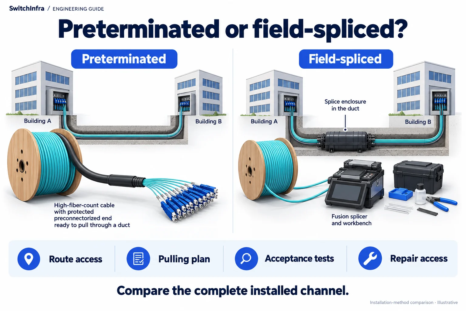
Compare factory-preterminated assemblies and field-spliced channels using the route, installation method and acceptance plan. Conceptual illustration; equipment shapes are illustrative.
Third-party project account · Independent analysis by SwitchInfra
Not a SwitchInfra deployment. Candidate equipment is proposed for comparable requirements.
3,456 — fibers per reported transport trunk
2 runs — preterminated field-trial sample
4-inch duct — reported route type
Anonymous — customer identity withheld
What the documented project tells us
Corning reports a Canadian expansion comparing preterminated and fusion-spliced interbuilding trunks. Its field trial used two 3,456-fiber preterminated runs and transition assemblies for in-building distribution; the customer is deliberately unnamed.
The practical choice is not whether one connector is universally faster. A buyer needs an installation approach that fits the route, presents usable distribution interfaces and can be accepted and repaired within the site’s operating constraints.
Project — An anonymous Canadian operator expanded to an adjacent building.
Scale — The transport-trunk fiber count is reported as 3,456.
Comparison — Preterminated and fusion-spliced approaches were compared on site.
Transition — The account describes 24-fiber to 12-fiber distribution transitions.
Scope of the analysis: Public project analysis of a third-party supplier account. Not a SwitchInfra deployment or independent acceptance report. Every proposed rate and model below is a separate design exercise.
Work through the engineering choices
Start with the documented constraint, then state the conditions for the proposed equipment role.
Compare complete installation work packages
The source describes both field splicing and a preterminated trial.
Design exercise: Design exercise: request two options for the same interbuilding capacity.
Give both bidders the same route, handoff interfaces and acceptance requirements. Include cable pulling, enclosure installation, fiber preparation, termination, patching and testing. A comparison that removes splicing labor but adds uncounted transition work will not predict the actual project cost or outage window.
Survey duct access, pulling arrangements, assembly dimensions, bend limitations and intermediate work areas. Check whether installation can proceed while the existing service stays intact. The trial’s construction conditions and crew experience should inform questions; they cannot establish another site’s completion date.
Corning Canadian field-trial report
Trace every transition to an equipment-facing channel
The report describes transport-to-distribution interface transitions.
Design exercise: Design exercise: allocate a small set of service channels from a large trunk.
Map the connector positions through transport enclosures, transition trunks, cassettes and patching. Keep physical fiber count separate from available service count. A 24-fiber transport termination is not itself an MPO-12 optical interface, nor evidence that a particular switch port supports breakout.
Establish the actual media grade before selecting active parts. For a hypothetical suitable single-mode channel, SFP-10G-LR or QSFP-100G-CWDM4-S may serve different endpoint requirements. Their inclusion here does not identify the trial’s optics or imply the reported transport assembly used that media.
CommScope cassette and distribution reference · Cisco 10G optical module data sheet · Cisco 100G optical module data sheet
Accept the delivered channel and its repair process
The supplier comparison includes installation and testing activities.
Design exercise: Design exercise: define handover for a new building connection.
Budget loss for all assemblies and mating points, using manufacturer definitions consistently to avoid counting the same connector twice. Require traceable test results for the channels being placed into service, with a clear record of repaired or reserved fibers.
If a longer single-mode service warrants QSFP-100G-LR4-S, evaluate its exact optical limits, host support and endpoint pairing. Nominal reach cannot compensate for an unknown transition map. Also agree how a damaged assembly can be isolated or replaced without confusing neighboring services.
Cisco 100G optical module data sheet · Cisco optics compatibility matrix
Quote the service-ready outcome
Compare installed cost and practical recovery alongside labor estimates. The desired quotation states what interfaces will be available, what evidence will accompany them and how spare capacity remains identifiable after handover.
Cisco optics compatibility matrix
Installation
Route survey, protected assembly dimensions, sequence and available work areas.
Mapping
Transport transitions, media, complete pairs and equipment-facing ports.
Acceptance
Channel loss records, defects, spare inventory and repair responsibilities.
Candidate models and selection boundaries
These are illustrative model inquiries, not the equipment installed in the source project. Confirm the required rate and complete channel before finalizing any line.
| Model / family and status | Role and condition |
|---|---|
| SFP-10G-LR Conditional model inquiry | Hypothetical 10G SMF service handoff Only after media, full channel and hosts are verified. Cisco 10G optical module data sheet |
| QSFP-100G-CWDM4-S Conditional model inquiry | Independent 100G SMF example Host/FEC and total channel loss require review. Cisco 100G optical module data sheet |
| QSFP-100G-LR4-S Conditional model inquiry | Alternative longer-reach 100G SMF example Not evidence of installed trial equipment. Cisco 100G optical module data sheet |
Listed models are independent design candidates, not equipment identified in this project. IDs are supplied only for previously verified exact catalog matches. Other PIDs are model inquiries; supply and platform compatibility are unconfirmed.
Continue in the relevant product family
Use the analysis to define the role before comparing catalog options.
Discuss this project
Carry the route, media, endpoint and loss requirements into the inquiry. Leave unknown quantities blank; source-project fiber counts are not an equipment BOM.
Follow the next selection question.
Compare related decisions while keeping each source’s scope, hardware and link conditions separate.
Browse more engineering analyses →
Single-mode university data center: 100G / 40G selection
A G.657.A2 fiber plant makes the complete optical channel central to the equipment choice.
Read the engineering analysis · Original project account
Expand mixed OM4 and single-mode cabling
A public Xi’an expansion account becomes a practical guide to channel allocation, 1U fiber density and patching-loss budgets.
Read the engineering analysis · Original project account
Global network BOMs: control substitutions
Standardize service requirements while retaining local channel and host configurations.
Read the engineering analysis · Original project account
Before you finalize the channel
Is the field trial a universal installation-time guarantee?
No. Site route, labor, assembly design, access and the work included in the comparison can change the outcome.
Does 3,456 fibers mean 3,456 active links?
No. Service capacity depends on fiber allocation, terminations, complete paths, reservations and equipment interfaces.
Are the proposed optical models part of Corning’s trial?
Their installation is not disclosed. They illustrate separately specified handoff requirements only.
What belongs in a fair two-option RFQ?
The same route, service interfaces, channel quantities, acceptance evidence, repair requirements and installation boundaries for each option.
Trace the project facts and technical limits
- Corning project account
- CommScope cassette and distribution reference
- Cisco 10G optical module data sheet
- Cisco 100G optical module data sheet
- Cisco optics compatibility matrix
Source check: 19 October 2026. Catalog status is stated per candidate.
Sources checked 19 October 2026. The PDF is revised February 2023; an exact publication day is unverified. Customer identity is withheld by the source. Proposed media and optics remain design assumptions.