Network solutions
Design the Passive Fiber Path Before Choosing the Optical Engines
Plan the passive fiber route, connector layout and branch locations before selecting the optical engines.
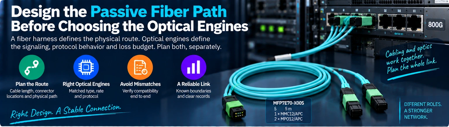
A passive fiber harness is one part of an optical link. It determines the physical route and channel connections, while the optical engines determine signaling, protocol behavior and the available loss budget. Keeping those responsibilities separate helps a structured-cabling plan remain useful when switches or adapters change.
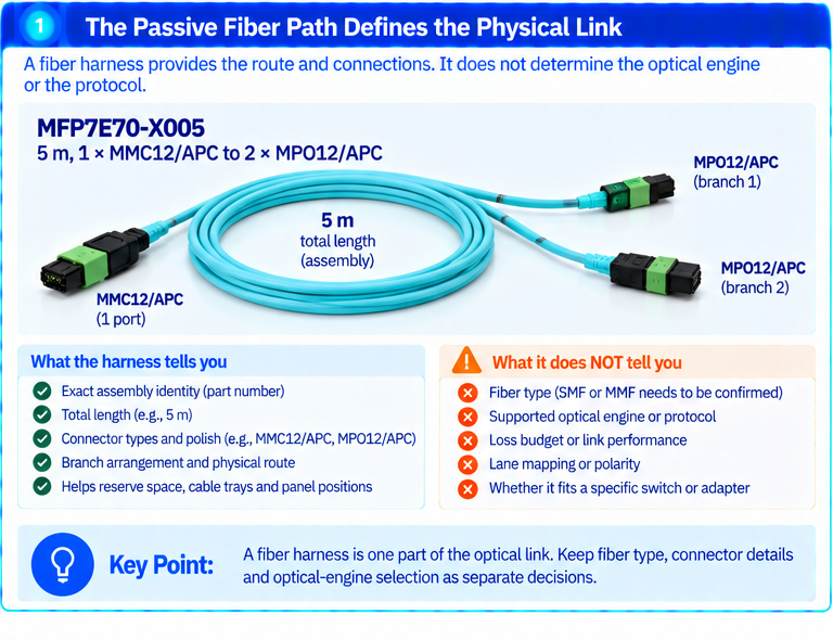
The owner-confirmed MFP7E70-X005 entry supplies a concrete assembly identity: 5 m, one MMC12/APC connection and two MPO12/APC branches. Those fields can be used to reserve route length and branch locations. The same source set contains conflicting MMF and SM wording, so the fiber-type decision stays separate until clarified. This single ambiguity does not erase the product identity or its connector arrangement.
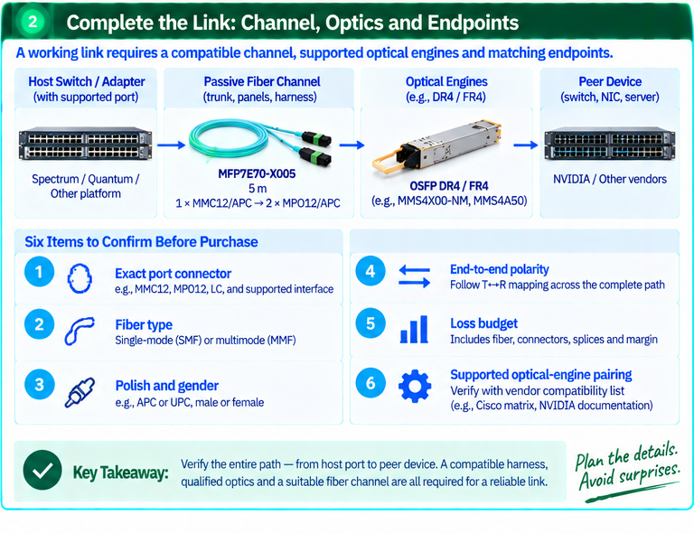
US Conec’s MMC guidance covers both single-mode and multimode technology. Therefore, “MMC” alone cannot resolve the fiber type. Its polarity guidance also emphasizes transmitter-to-receiver mapping across the complete path. Create a channel schedule for the trunk, patch panels, harness and destination optics; connector count alone is not a lane map.
NVIDIA’s Spectrum-6 documentation illustrates another reason to be precise: it describes a 16-position MMC interface for SN68x0-LD systems. That interface is not proof that an MMC12 assembly fits. Similarly, NVIDIA’s Q3450 topology list names specific CPO-interoperable optics. A general CPO description does not qualify every DR4 module or fiber harness for those endpoints.
For a practical review, collect six items: exact port connector, fiber type, polish and gender, end-to-end polarity, loss budget and supported optical-engine pairing. Preserve the manufacturer’s distinction between parallel DR4 and wavelength-multiplexed FR4. Then verify link operation and retain the installed channel map. The result is a serviceable optical path with known boundaries, rather than an unsupported compatibility promise.
Scope: Documented technology and an original design workflow; no exact MFP7E70 deployment or host qualification is asserted.
Public references
- US Conec MMC Connectors
- US Conec MMC Speed of Deployment: Compatibility and Polarity Management
- NVIDIA Interconnect for Spectrum-6 Based Ethernet Switches | NVIDIA Spectrum-6 SN6000 Switch Systems Hardware User Manual
- Accessory and Replacement Parts | NVIDIA Q32xx and Q34xx XDR 800Gb/s InfiniBand Switch Systems User Manual
- MMS4X00-NM 800Gbps Twin-port OSFP 2x400Gb/s InfiniBand and Ethernet Single Mode 2xDR4 500m | MMS4X00-NM 800Gbps Twin-port OSFP 2x400Gb/s InfiniBand and Ethernet Single Mode 2xDR4 500m
- NVIDIA MMS4A50 1600Gbps, OSFP, 2xLC-LC, 1310nm SMF, 2xFR4 Twin-port Transceiver (up to 2km) | NVIDIA MMS4A50 1600Gbps, OSFP, 2xLC-LC, 1310nm SMF, 2xFR4 Twin-port Transceiver
Technical illustrations