
400G Data Center Design Guide: Ports, Capacity, Optics and Acceptance
Build a 400G fabric worksheet covering endpoint demand, uplink ratios, physical channels, software features and evidence-based acceptance.
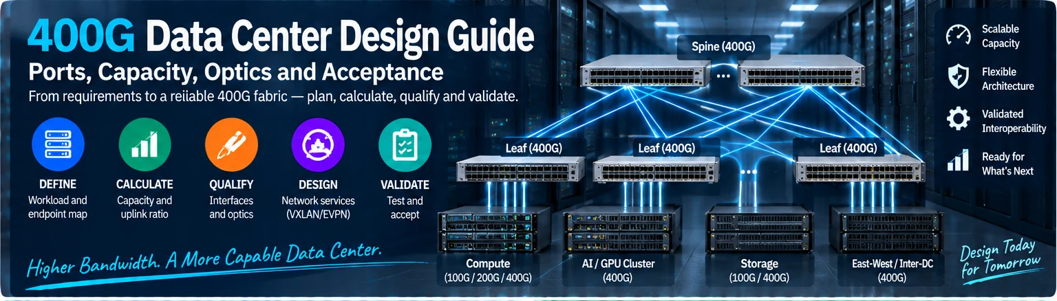
This guide provides a design worksheet for a 400G data-center network. It does not prescribe a universal topology or claim that every device labeled 400G is interchangeable. Complete the calculations and qualification records before converting the design into a BOM.
1. Define the workload and endpoint map
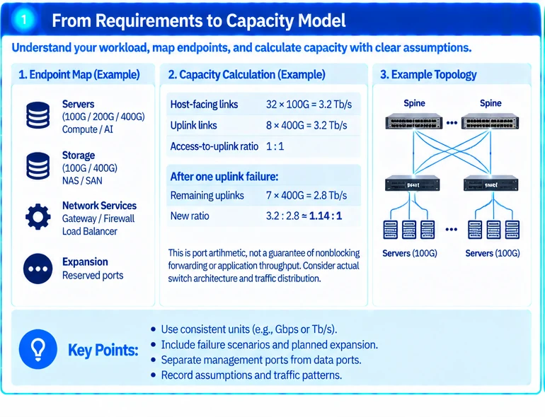
Record the server and storage interfaces, traffic direction, expected concurrency and application objectives. Distinguish nominal endpoint rates from measured demand. Identify the requirement under maintenance or failure, not only under normal operation.
Create a port schedule showing host-facing links, inter-switch links and the next planned expansion. Management ports belong in a separate schedule.
2. Calculate capacity explicitly
Use consistent units and show the assumptions:
access capacity = active endpoint-facing links × rate per link
uplink capacity = active uplinks × rate per uplink
access-to-uplink ratio = access capacity ÷ uplink capacity
For an illustrative leaf with thirty-two 100G host links and eight 400G uplinks, both sums equal 3.2 Tb/s. One failed uplink leaves 2.8 Tb/s, changing the ratio from 1:1 to approximately 1.14:1. This is port arithmetic, not a proof of nonblocking forwarding or application throughput.
Record how the actual switch architecture, traffic distribution and failure domain affect that model.
3. Qualify every interface implementation
| Layer | Required record |
|---|---|
| Host | Exact device, port and supported operating mode |
| Interconnect | Full module or assembly identifiers at both ends |
| Optical path | Optical specification, fiber, connectors, mapping and loss limits |
| Software | Release, required features and applicable support conditions |
| Installation | Cooling, power, mounting and service access |
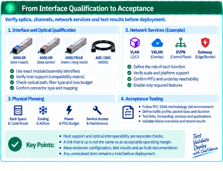
Check host support separately from optical interoperability. A compatible connector and common rate do not establish a qualified path. R25R49
4. Define the network services
Specify routing, segmentation, gateway placement and any overlay requirement. VXLAN encapsulation and EVPN control-plane behavior address different parts of an overlay design. Retain underlay reachability, MTU and operational responsibilities in the configuration plan. R30R31
Avoid enabling a feature solely because it is available. Every additional control mechanism should serve a stated requirement and have a validation method.
5. Review physical density
Count modules, cable routes, panel positions and maintenance clearances. Include thermal and power requirements for the exact populated configuration. A rack-unit density advantage can disappear if the design leaves insufficient space for connectors or replacement work.
The BOM should distinguish required installed parts from spares and candidates awaiting qualification.
6. Define acceptance before staging
Specify traffic profile, packet sizes, direction, duration and pass criteria. Use suitable isolated facilities for disruptive benchmarking. RFC 2544 provides laboratory methodology, while RFC 6815 cautions against its uncritical use on production networks. R46R47
Validate physical links, forwarding, intended services and representative applications in separate stages. Test approved faults and record remaining capacity and service impact.
The completed design package contains a capacity model, port map, qualified interconnect matrix, software baseline and acceptance plan. Together they establish what the 400G network is intended to achieve and how that conclusion will be supported.
Engineering illustrations
These figures illustrate the design concepts discussed here. They are not measured results, certified configurations or a supplied-equipment list.
References
- R25: Cisco 100GBASE QSFP Modules Data Sheet
- R49: Cisco transceiver-to-device compatibility matrix
- R30: RFC 7348: Virtual eXtensible Local Area Network (VXLAN)
- R31: RFC 8365: A Network Virtualization Overlay Solution Using EVPN; RFC 7432: BGP MPLS-Based EVPN
- R46: RFC 2544: Benchmarking Methodology for Network Interconnect Devices
- R47: RFC 6815: Applicability Statement for RFC 2544