
Modular Campus Core Selection: Verify Chassis, Supervisor and Line-Card Dependencies
Select a modular campus switching system through a dependency matrix covering control, forwarding, interfaces, power and software.
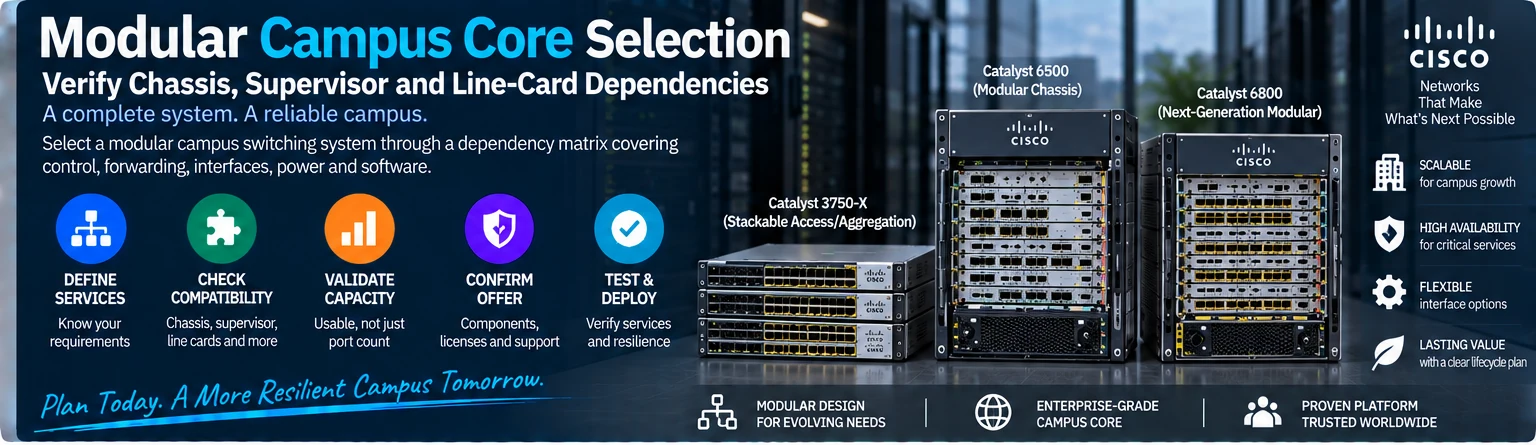
A modular campus switch is selected as a complete system. Chassis slots, supervisors, line cards, power and software have interdependent requirements. Use this guide to review an offered configuration or plan a supported expansion without treating the line-card port count as the capacity of a complete switch.
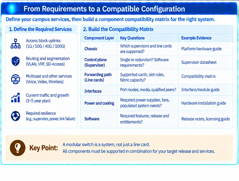
1. Define the required services
Record access-block uplinks, routing functions, segmentation, multicast or other required services, and the failure condition the core must tolerate. Identify current traffic and the next planned expansion.
Choose the campus architecture before selecting a chassis. A modular system is not automatically necessary for every aggregation role; the operating and growth requirements should justify it. R45
2. Build the compatibility matrix
| Component layer | Required evidence |
|---|---|
| Chassis | Supported supervisors, slot roles and mechanical requirements |
| Control plane | Supervisor combination, software and redundancy behavior |
| Forwarding path | Line-card support, slot/fabric capacity and feature constraints |
| Interfaces | Required port modes, media and qualified peers |
| Power and cooling | Approved assemblies and populated-system requirements |
| Software | Required functions, release and applicable entitlements |
Use documentation for the exact platform generation. A supervisor paper for a specific Catalyst 6500/6800 configuration does not establish support for a different modular family. R26
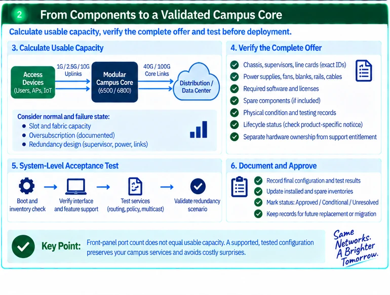
3. Calculate usable capacity
Add the intended interface demand, then check the actual slot and fabric path. Repeat the calculation under the agreed component failure. Do not assume that front-panel port-rate sums are simultaneously available across every internal path.
As an illustrative review, a line card with many access ports may be suitable for the expected concurrency while still oversubscribed relative to its system connection. That can be an intentional design choice, but it must be documented rather than described as universally nonblocking.
4. Verify the complete offer
Separate the chassis, required installed components, optional parts and spares in the packing list. Identify blanks, mounting hardware, power cords and management accessories where required. A populated marketing photograph is not evidence that those items are included.
Confirm software and support conditions independently of physical possession. For older systems, check the exact lifecycle notices rather than deriving dates from a general policy. R19
5. Prepare a system-level acceptance test
Verify inventory, environmental state and intended interfaces before introducing services. Test the required routing and policy functions, representative traffic and the approved redundancy scenario. Record the configuration and component inventory with the results.
Where a supervisor or line-card change alters the supported software baseline, include that dependency in the migration plan. Do not hide a necessary platform upgrade inside a nominal spare replacement.
The completed record should demonstrate why the offered system meets the defined role and which conditions remain unresolved. It provides a defensible basis for comparison between configurations that may look similar at the front panel but differ substantially in usable capability and completeness.
Engineering illustrations
These figures illustrate the design concepts discussed here. They are not measured results, certified configurations or a supplied-equipment list.
Related reading
- Campus Core Design: Chassis Dependencies, Capacity and Resilience
- Buying a 48-Port Line Card? Check the System Behind the Ports
References
可直接使用的项目资料
按当前任务选择资料。可以先提交已有清单,后续再补缺项。下载模板为英文。