
Cisco · campus-core
Campus Core Design: Chassis Dependencies, Capacity and Resilience
Design campus aggregation and core switching around the complete platform, failure-state capacity and a staged service migration.
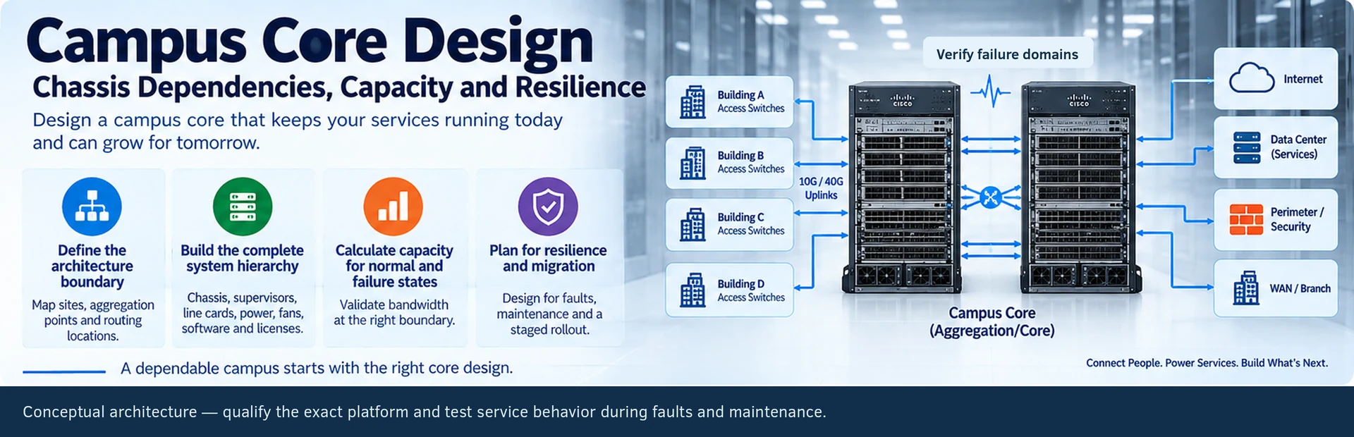
A campus core is a service dependency shared by many access blocks. Its design should explain where routing happens, which failures remain local and how the platform behaves during maintenance. Port count is only one part of that decision.
This solution covers aggregation and core planning for a campus refresh or expansion. It applies to a modular system only after the complete chassis configuration has been identified; a line-card quotation is not a core-network design.
Choose the architectural boundary
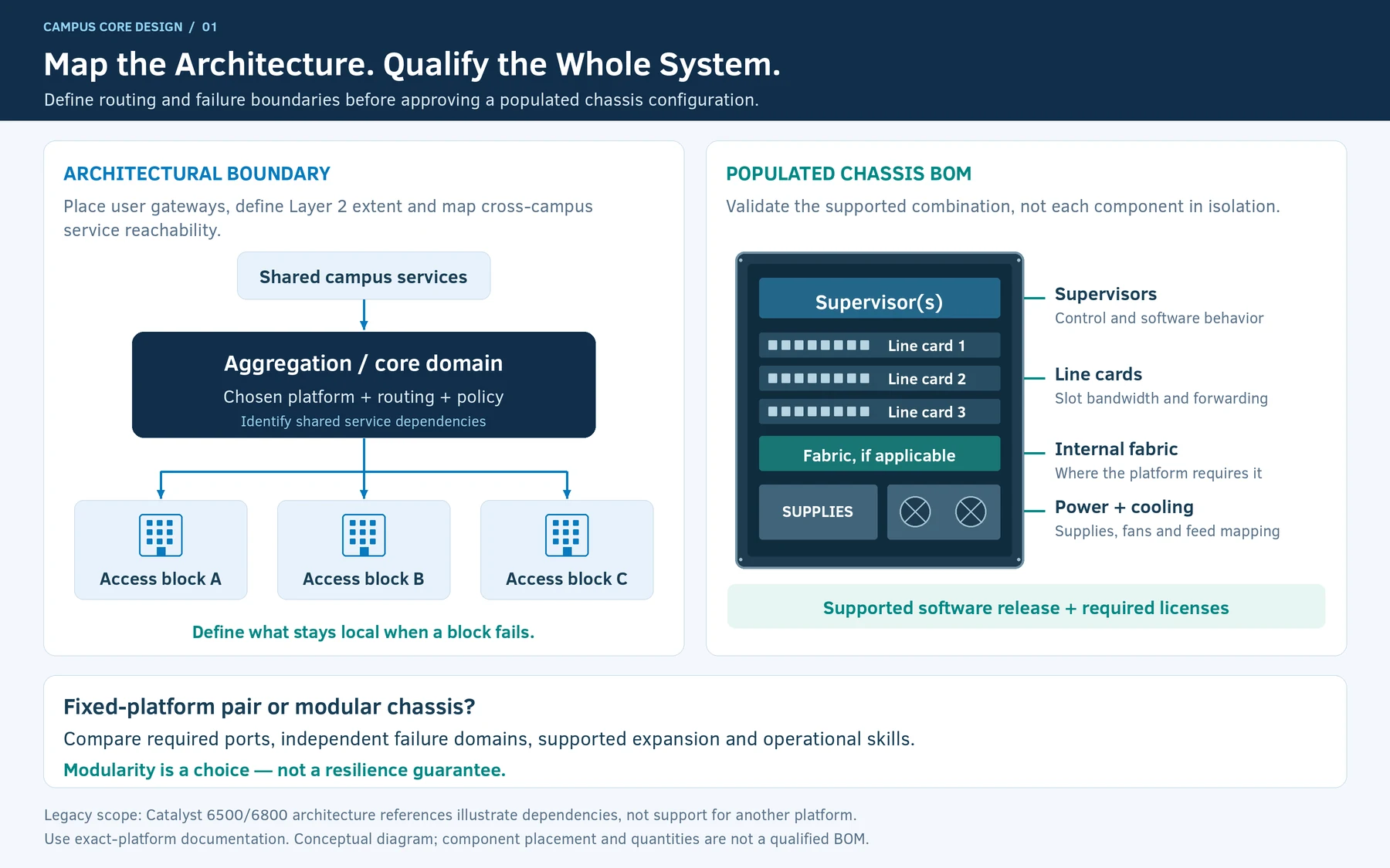
Map buildings or access blocks to their aggregation points. Identify whether Layer 2 extends between them, where user gateways are placed and which services require cross-campus reachability. Prefer a design whose failure behavior can be explained without tracing every access port through the entire campus.
A fixed-platform pair and a modular chassis may both satisfy a requirement. Compare the required ports, independent failure domains, expansion method and operational skills. Modularity is useful when the supported expansion path fits the project; it is not inherently a reason to choose a larger shared chassis.
Build the complete system hierarchy
For a modular design, list chassis, supervisors, line cards, fabric components where applicable, supplies, fans, software and licenses. Validate combinations rather than checking each component in isolation. Cisco’s historical Catalyst 6500/6800 architecture material illustrates why supervisor and line-card dependencies are part of the system definition. R26
Keep that legacy-platform scope explicit. It is not a substitute for the documentation of a different current Catalyst family, and it does not establish support for an arbitrary mixed-generation configuration.
Calculate capacity at the relevant boundary
Sum required uplinks by access block, then examine slot bandwidth, forwarding behavior and the selected interconnection design. Do not mix one-direction interface capacity with a vendor’s bidirectional switching-capacity figure.
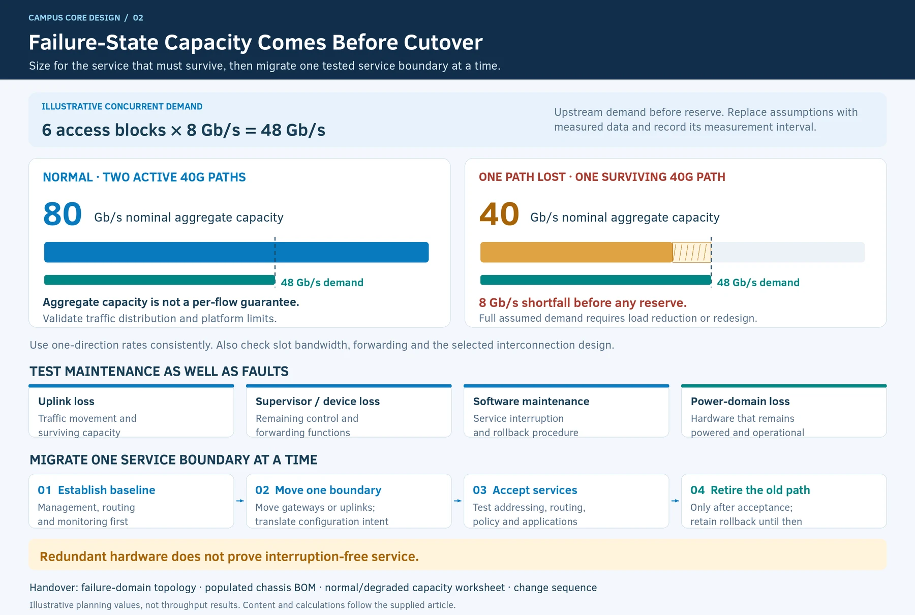
As an illustrative failure-state calculation, six access blocks with 8 Gb/s of concurrent upstream demand require 48 Gb/s before reserve. A design with two active 40G paths has 80 Gb/s of nominal aggregate capacity normally, but only 40 Gb/s after losing one. It cannot preserve the assumed full demand under that fault without reducing load or changing the design.
The calculation is intentionally based on assumed demand rather than the sum of endpoint link rates. Record the origin and measurement interval of real demand figures when replacing the assumptions.
Design maintenance as well as fault recovery
| Event | Question to resolve |
|---|---|
| Uplink loss | Which traffic moves, and is surviving capacity sufficient? |
| Supervisor or device loss | Which control and forwarding functions remain available? |
| Software maintenance | Which services are interrupted, and how is rollback performed? |
| Power-domain loss | Which hardware remains powered, not merely fitted with two supplies? |
Redundant hardware does not prove interruption-free service. Use the supported platform behavior and a testable application requirement.
Migrate one service boundary at a time
Establish management, routing and monitoring on the new platform before moving gateways or uplinks. Translate configuration intent rather than copying syntax across operating systems. Keep the old path available until addressing, routing, policy and application tests have passed.
The handover should include a topology with failure domains, populated chassis BOM, normal/degraded capacity worksheet and change sequence. Campus design guidance can frame the architecture, but the project’s own acceptance tests establish whether its requirements have been met. R45
Engineering illustrations
These figures illustrate the design concepts discussed here. They are not measured results, certified configurations or a supplied-equipment list.
Related reading
- Modular Campus Core Selection: Verify Chassis, Supervisor and Line-Card Dependencies
- Buying a 48-Port Line Card? Check the System Behind the Ports