
Cisco · long-reach
Long-Reach 10G Fiber Design: Loss Budget, Receiver Limits and Acceptance
Engineer long-reach 10G links using worst-case optical power, channel loss, dispersion and measured acceptance criteria.
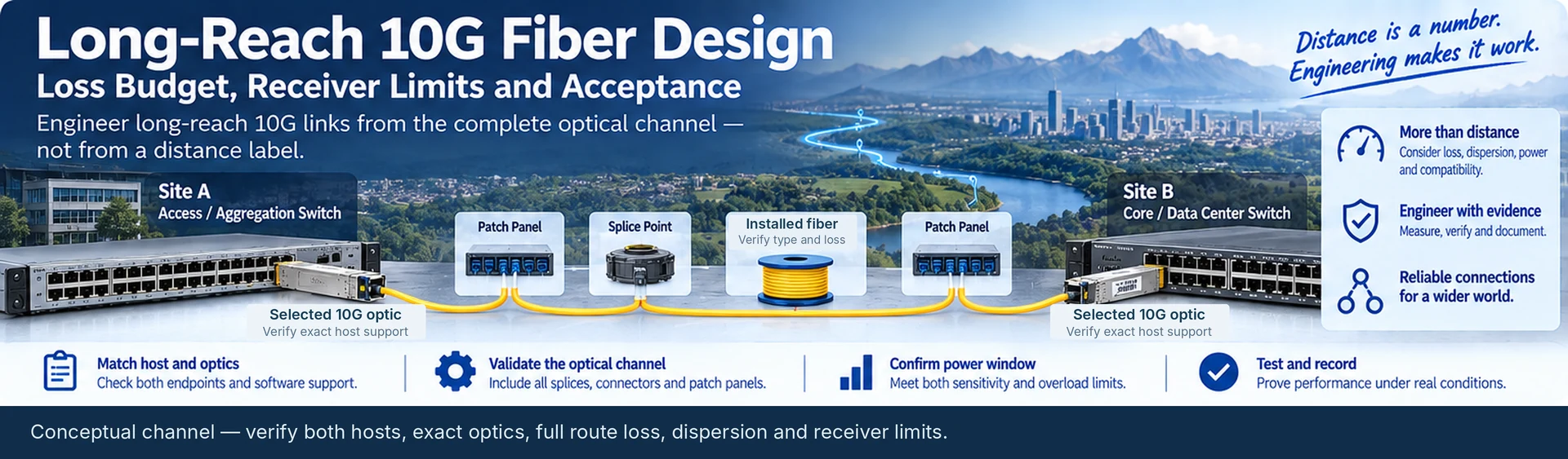
A distance label does not qualify a long-reach link. The same route length can contain different fiber, splice counts and connector losses, while a short route can deliver too much optical power to a receiver. Design a long-reach 10G connection from the exact transmitter, receiver and installed channel—not from kilometers alone.
Establish the actual service and route
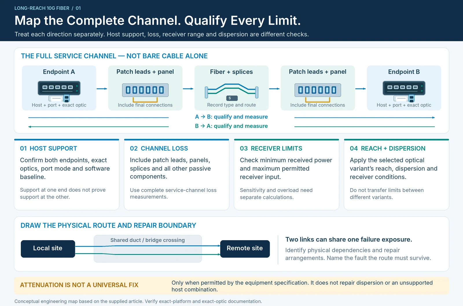
Confirm that both endpoints support the selected optics and required port mode. Record the physical route, fiber type, patching points, splice records and available loss measurements. Treat each direction as a separate optical path when its components or measurements differ. A supported transceiver at one endpoint does not establish support at the other. R49
The route record should also identify repair arrangements. A nominally redundant connection sharing the same duct or bridge crossing may not protect the failure the project is intended to survive.
Calculate a power window, not just a maximum distance
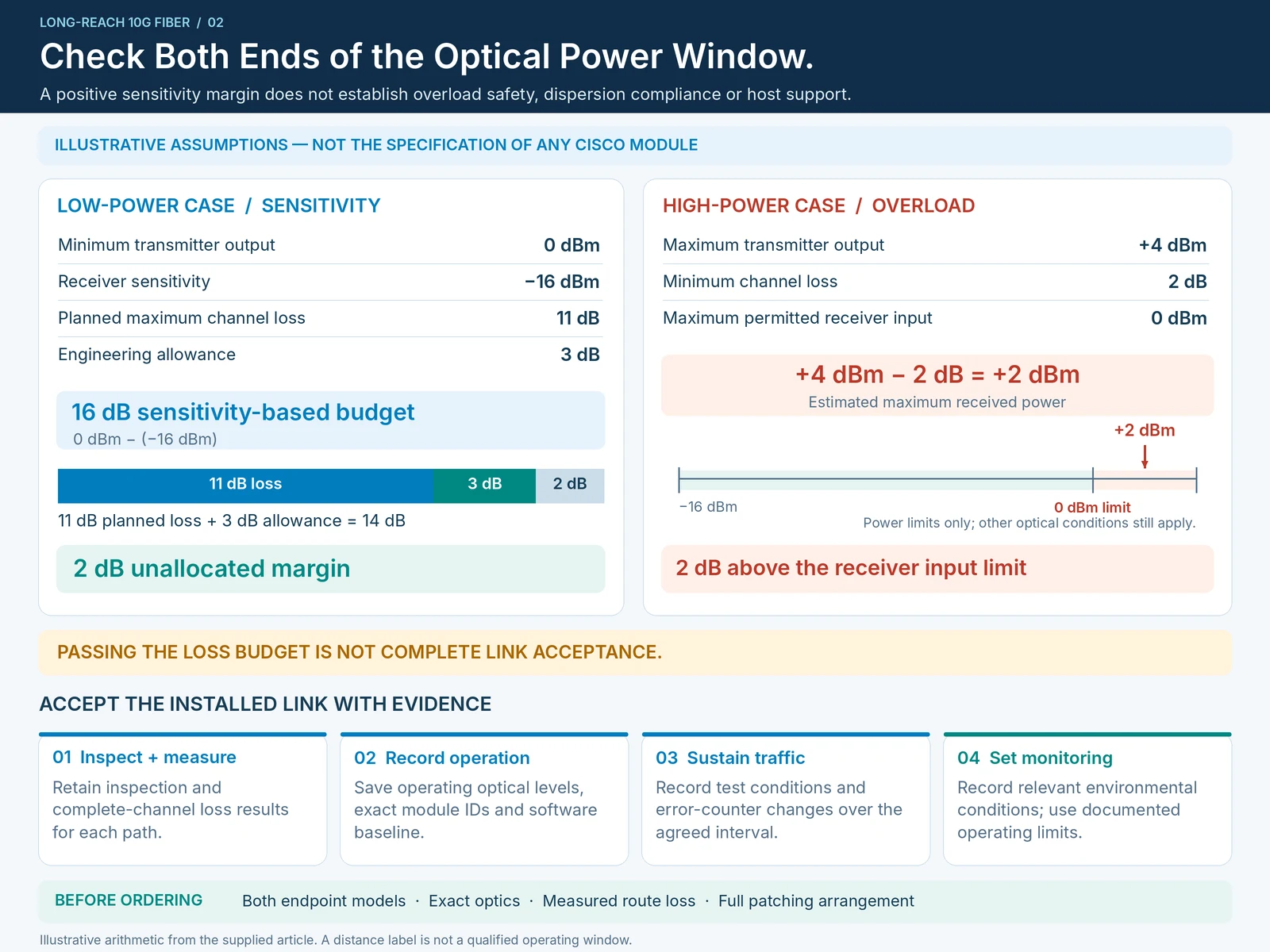
For a simple passive channel, the minimum received power is estimated from minimum transmitter output minus maximum channel loss. Compare that result with the receiver sensitivity, including a justified engineering allowance. At the other extreme, maximum transmitter output minus minimum channel loss must not exceed the receiver’s permitted input.
Consider an illustrative calculation, not the specification of any Cisco module:
| Assumed quantity | Value |
|---|---|
| Minimum transmitter power | 0 dBm |
| Receiver sensitivity | −16 dBm |
| Planned maximum channel loss | 11 dB |
| Reserved engineering allowance | 3 dB |
The sensitivity-based budget is 16 dB; planned loss plus allowance is 14 dB, leaving 2 dB of unallocated margin. That result alone says nothing about overload or dispersion. If the assumed maximum transmitter output were +4 dBm, minimum channel loss 2 dB and maximum receiver input 0 dBm, the estimated +2 dBm received level would exceed the limit.
Resolve limits that the loss equation does not cover
Read the selected optic’s reach, dispersion and receiver conditions as well as its power figures. Attenuation may address excessive received power when permitted by the equipment specification, but it does not repair a dispersion mismatch or an unsupported host combination. Cisco’s 10G module documentation distinguishes the requirements of individual optical variants; do not transfer one variant’s limits to another. R18
Loss measurements should include the complete service channel. A measurement of bare cable is not a substitute for the final route through patch leads, panels and other passive components.
Accept the installed link with evidence
Retain inspection and loss results, measured operating levels, module identifiers, software baseline and traffic-test conditions. Check error-counter changes during sustained traffic and document environmental conditions relevant to the deployment. Configure monitoring against documented limits rather than arbitrary alarm values.
The result is a qualified channel with a defined operating margin. Before ordering, supply both endpoint models, exact optics under consideration, measured route loss and the full patching arrangement. This information supports an engineering decision; a request for “80 km SFPs” does not.
Engineering illustrations
These figures illustrate the design concepts discussed here. They are not measured results, certified configurations or a supplied-equipment list.
Related reading
- SFP-10G-ZR Qualification: Check Both Loss Margin and Receiver Overload
- An 80 km Optic Is Not an 80 km Link Guarantee