
Network engineering
Data Center Fiber Cabling: Engineer and Test the Complete Optical Channel
Design data-center fiber paths by optical interface, connector mapping, channel loss and application-specific acceptance.
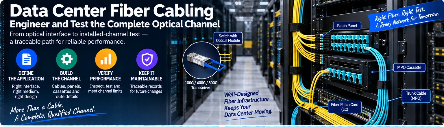
Fiber selection begins with the optical interface and ends with an installed-channel test. Between those points are patch leads, panels, cassettes, connectors and route constraints that can change whether the link meets its requirements. Treating the cable reel as the entire channel leaves those dependencies unresolved.
Define the application at both endpoints
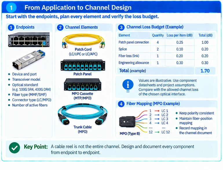
Record device, port, transceiver and intended mode at each end. Identify the specified fiber medium, active fiber count and connector arrangement. Similar line rates can use different optical implementations, so a description such as “100G fiber” is not sufficient. R25
Separate duplex-fiber and parallel-fiber designs. Do not assume that a cassette turning a trunk into several duplex pairs converts the optical interface carried by the endpoints. It redistributes physical paths; the active interfaces must still be compatible.
Build a channel schedule
| Channel element | Required information |
|---|---|
| Endpoint modules | Exact identifiers and optical specifications |
| Patch leads | Fiber type, length and connector details |
| Panels and cassettes | Mating arrangement, mapping and specified loss |
| Trunk | Fiber category, routed length and termination |
| Intermediate work | Splices, additional connections and route exceptions |
| Acceptance | Test method, limits and result file linked to the channel ID |
For multi-fiber systems, preserve polarity and fiber-position mapping through every component. A channel can be physically connected and still route a transmitter to the wrong receiver position. R42
Add the losses before approving the route
Use the selected components’ documented limits and the project’s installation assumptions. For a purely illustrative estimate, four connections budgeted at 0.25 dB each, two splices at 0.10 dB each and 0.20 dB of fiber loss sum to 1.40 dB. Adding a 0.30 dB engineering allowance gives a 1.70 dB design requirement.
Those values are not universal connector or splice specifications. Compare the actual project calculation with the allowed channel loss of the chosen optical interface, and include other relevant constraints. A favorable loss estimate does not establish compatibility with a different optical standard.
Test what was actually installed
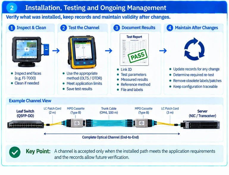
Inspect and clean connections as appropriate before measurement. Use the documented reference method and test setup for the channel; retain enough information to reproduce the result. Inspection tools address end-face condition, while channel tests establish different properties. R17
Where parallel optics are used, a single passing fiber does not qualify every active lane. Retain the relevant per-fiber or channel evidence and investigate unexpected variation rather than averaging away a problem.
Keep qualification valid after changes
A replaced patch lead, added cassette or rerouted segment changes the channel record. Determine which checks must be repeated and update the accepted configuration. Do not attach an old test report to a physically different path.
The handover should identify the optical application each channel was qualified for, not merely state that “fiber passed.” This makes later speed upgrades and spare substitutions reviewable instead of relying on cable color or an incomplete label.
Engineering illustrations
These figures illustrate the design concepts discussed here. They are not measured results, certified configurations or a supplied-equipment list.
Related reading
- SFP+, QSFP28 and QSFP-DD Selection: Form Factor Is Only the First Filter
- Data Center Fiber Selection Worksheet: Medium, Mapping and Channel Limits