
Network engineering
High-Speed Data Center Cabling: Match Interfaces, Routes and Service Boundaries
Plan high-speed interconnects with explicit logical links, endpoint compatibility, cable routes and serviceable replacement methods.

At higher interface rates, cable selection becomes a coordination task between the server, switch and physical installation. The relevant question is not simply whether an assembly is labeled 400G or 800G. It is whether that assembly implements the intended logical links, is supported at both endpoints and can be installed and serviced correctly.
Count logical links before ordering components
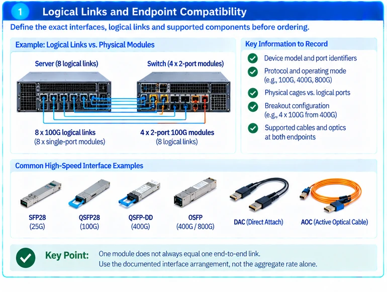
Create an endpoint schedule showing device, port, protocol and operating mode. Separate physical cages from logical ports and record every branch of a breakout assembly. A twin-port module may contain multiple independently used optical channels, so one module does not always equal one end-to-end link. R01
For an illustrative deployment, eight logical links might use eight separate modules at one end but four supported twin-port modules at the other. The actual module count depends on the documented interface arrangement; it must not be inferred from the aggregate capacity alone.
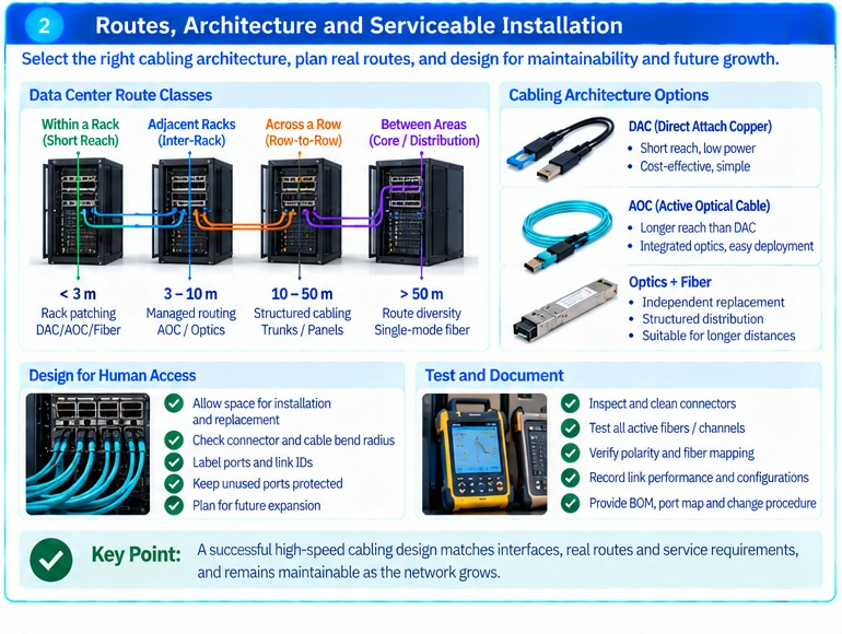
Divide the room into route classes
| Route class | Main selection concern |
|---|---|
| Within a rack | Supported assembly, connector access and managed slack |
| Between adjacent racks | Actual tray route and replacement practicality |
| Across a row | Structured patching, channel loss and clear ownership |
| Between network areas | Capacity reserve, route diversity and documented optical interfaces |
Measure routed length rather than equipment separation. Include the path needed to service a device without stressing connectors or obstructing airflow. Verify thermal form factors independently of mechanical fit; supported cooling arrangements can differ between hosts. R01
Choose a channel architecture
Use direct-attach assemblies where the exact implementation and route fit the design. Use separate optics and fiber where the service model calls for independent replacement or structured distribution. Do not prescribe one approach for every rate or distance.
For optical channels, preserve the selected physical-media specification, fiber type, active fiber count, connector mapping and applicable channel limits. A vendor catalogue identifies available implementations; it does not make all same-rate products interchangeable. R25
Plan high density around human access
A fully populated panel still needs room to identify, release, inspect and replace connections. Check service access with the intended connector and cable dimensions. A layout that maximizes ports per rack unit but prevents safe replacement is not necessarily the better installed design.
For multi-fiber systems, document polarity and fiber mapping through trunks and cassettes. Passive components organize fibers; they do not convert incompatible endpoint signaling. R42
Deliver qualified links with traceable spares
Commission representative paths before completing the full rollout. Record module recognition, link mode, diagnostics where available and error behavior under agreed traffic. Tie results to the exact installed configuration and retain the corresponding spare identifiers.
The handover should include a port map, route schedule, approved component combinations and a change procedure. For an enquiry, provide endpoint models, intended logical modes, rack layout and measured routes. That enables a high-speed cabling proposal grounded in the installation rather than a list of matching speed labels.
Engineering illustrations
These figures illustrate the design concepts discussed here. They are not measured results, certified configurations or a supplied-equipment list.
Related reading
- Optics and Cable Selection Checklist: Qualify Both Endpoints and the Channel
- 10G, 40G and 100G Short-Link Selection: DAC, AOC and SR-BD Checks