
Network engineering
Commissioning an 800G RoCE Fabric: A Layered Acceptance Plan
Validate an 800G RoCE deployment from physical links and host readiness to concurrent collectives, congestion and recovery.
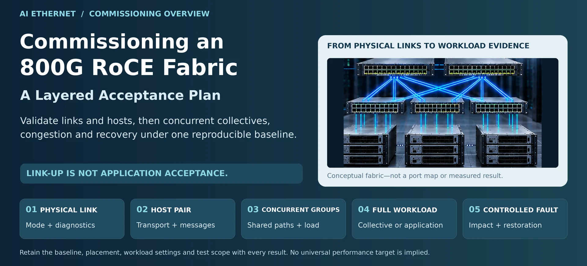
A RoCE fabric can bring every interface up and still deliver inconsistent application performance. Acceptance should therefore move through separate evidence layers: physical connectivity, host transport, fabric behavior and the application. Skipping a layer makes later failures harder to isolate.
Establish a reproducible baseline
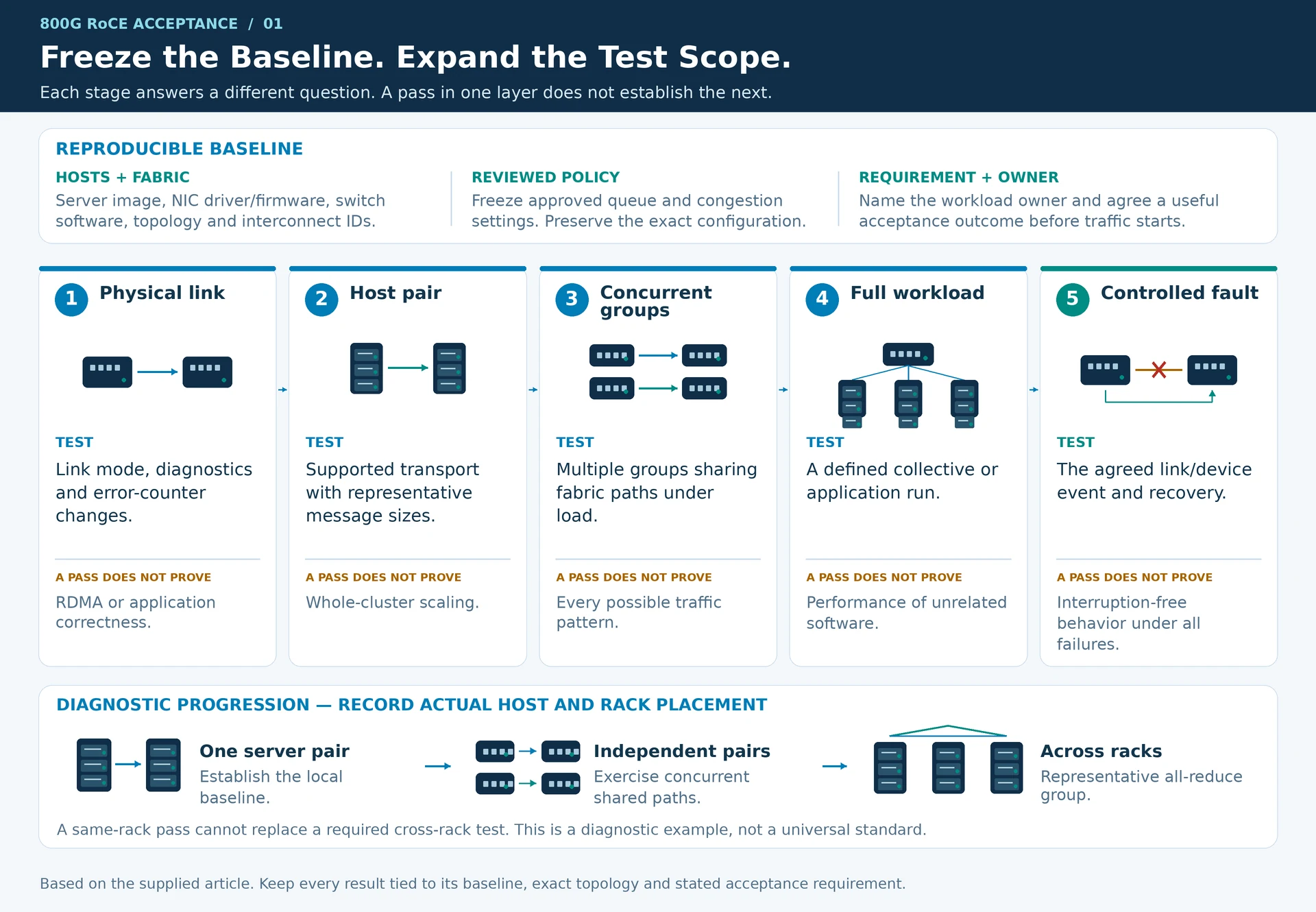
Freeze the server image, adapter driver and firmware, switch software, topology and interconnect inventory. Record the approved queue and congestion settings. Tests performed under different baselines should not be combined into one unexplained result.
Choose the workload owner and the acceptance criteria before running traffic. The criteria should describe a useful outcome—such as stable completion of a defined collective workload—rather than an arbitrary percentage of the port’s label rate.
Validate in increasing scope
| Stage | What to test | What a pass does not prove |
|---|---|---|
| Physical link | Mode, diagnostics and error-counter changes | RDMA or application correctness |
| Host pair | Supported transport and representative message sizes | Whole-cluster scaling |
| Concurrent groups | Multiple communicating groups and shared paths | Every possible traffic pattern |
| Full workload | Defined collective or application run | Performance of unrelated software |
| Controlled fault | Agreed link or device event and recovery | Interruption-free behavior under all failures |
At each stage, retain the precise topology and endpoint placement. A favorable same-rack result should not stand in for a cross-rack test when production jobs span the fabric.
Observe congestion while it happens
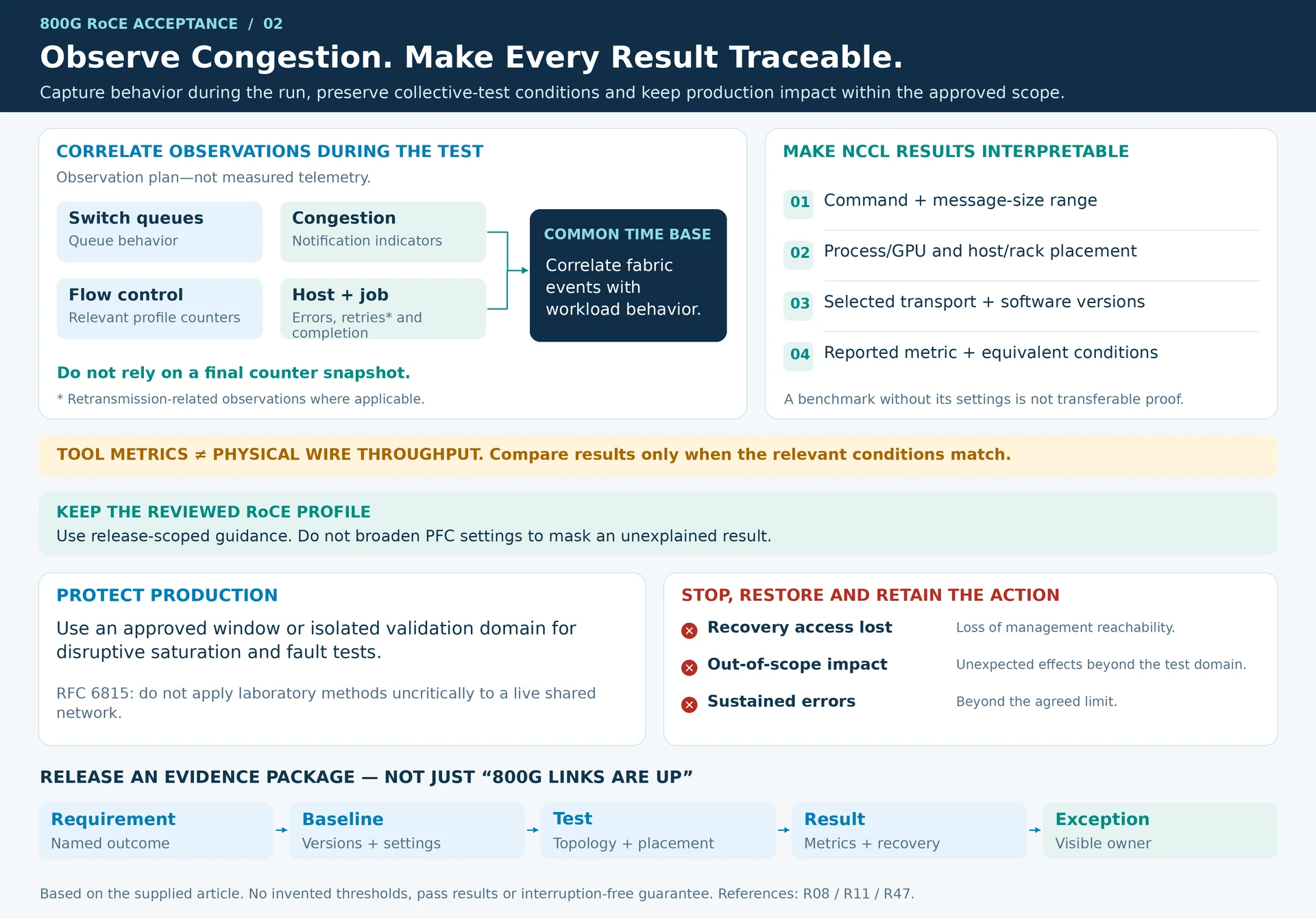
Capture queue, congestion-notification and relevant flow-control indicators during the test. Correlate them with endpoint errors, retransmission-related observations where applicable, and workload completion behavior. A final counter snapshot can hide when a problem occurred.
Use the selected release’s documented RoCE profile as the configuration reference. Avoid “fixing” an unexplained result by enabling broad PFC settings that were not part of the reviewed design. R08
Make collective results interpretable
For NCCL Tests or a similar tool, retain the command, message-size range, process/GPU placement, transport selection and software versions. Distinguish the metric reported by the tool from physical wire throughput. Compare results only when the relevant conditions match. R11
As an illustrative sequence, test one server pair, then several independent pairs, then a representative all-reduce group across racks. This is a diagnostic progression, not a universal performance standard or a guarantee that a particular tool exercises every application requirement.
Protect production during acceptance
Run potentially disruptive saturation and fault tests in an approved window or isolated validation domain. Laboratory benchmark methods should not be applied uncritically to a live shared network. R47
Stop conditions should include loss of management access, unexpected impact outside the test scope or sustained errors beyond the agreed limit. Record the restoration action as part of the result.
The acceptance package should link every result to a requirement and configuration baseline. Unresolved exceptions remain visible with an owner; they should not disappear behind the phrase “800G links are up.”
Engineering illustrations
These figures illustrate the design concepts discussed here. They are not measured results, certified configurations or a supplied-equipment list.
Related reading
- 800G RoCE Fabric Architecture for AI Clusters
- Link-Up Is Only the First Test of an AI Network
- Optics and Cable Selection Checklist: Qualify Both Endpoints and the Channel