
Network engineering
800G RoCE Fabric Architecture for AI Clusters
Design an 800G RoCE fabric from workload concurrency, host topology, congestion policy and qualified interconnects.
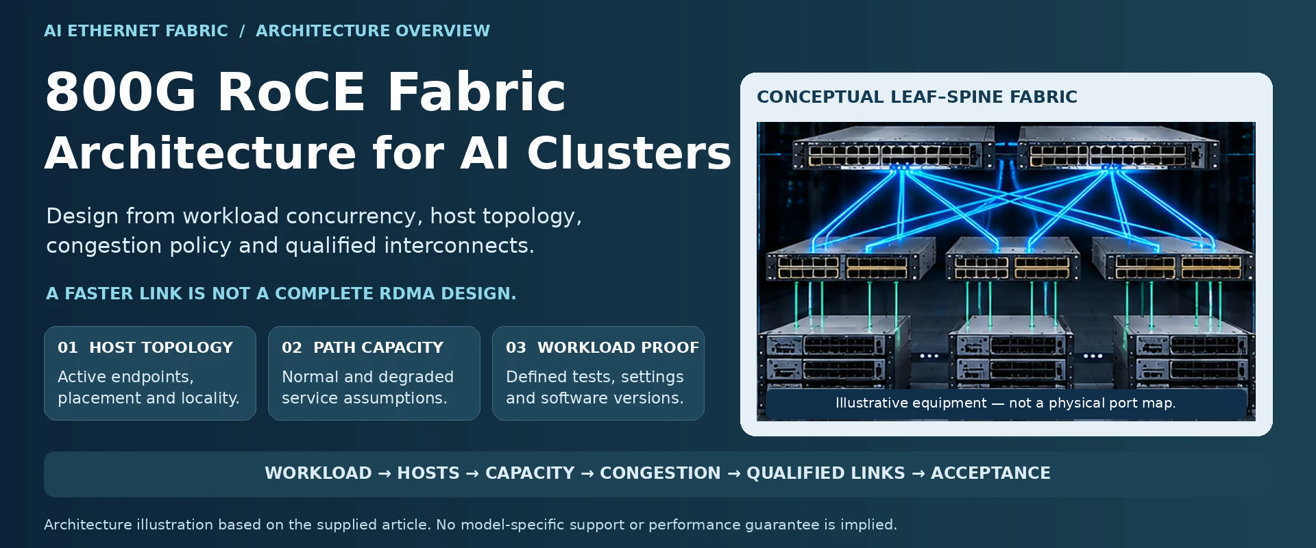
An 800G RoCE fabric is justified by the communication pattern of an AI workload, not by the availability of an 800G switch. The architecture must coordinate host attachment, path capacity and congestion behavior. A fast individual link cannot compensate for an undersized shared path or an incorrectly integrated RDMA stack.
Map communication to the server topology
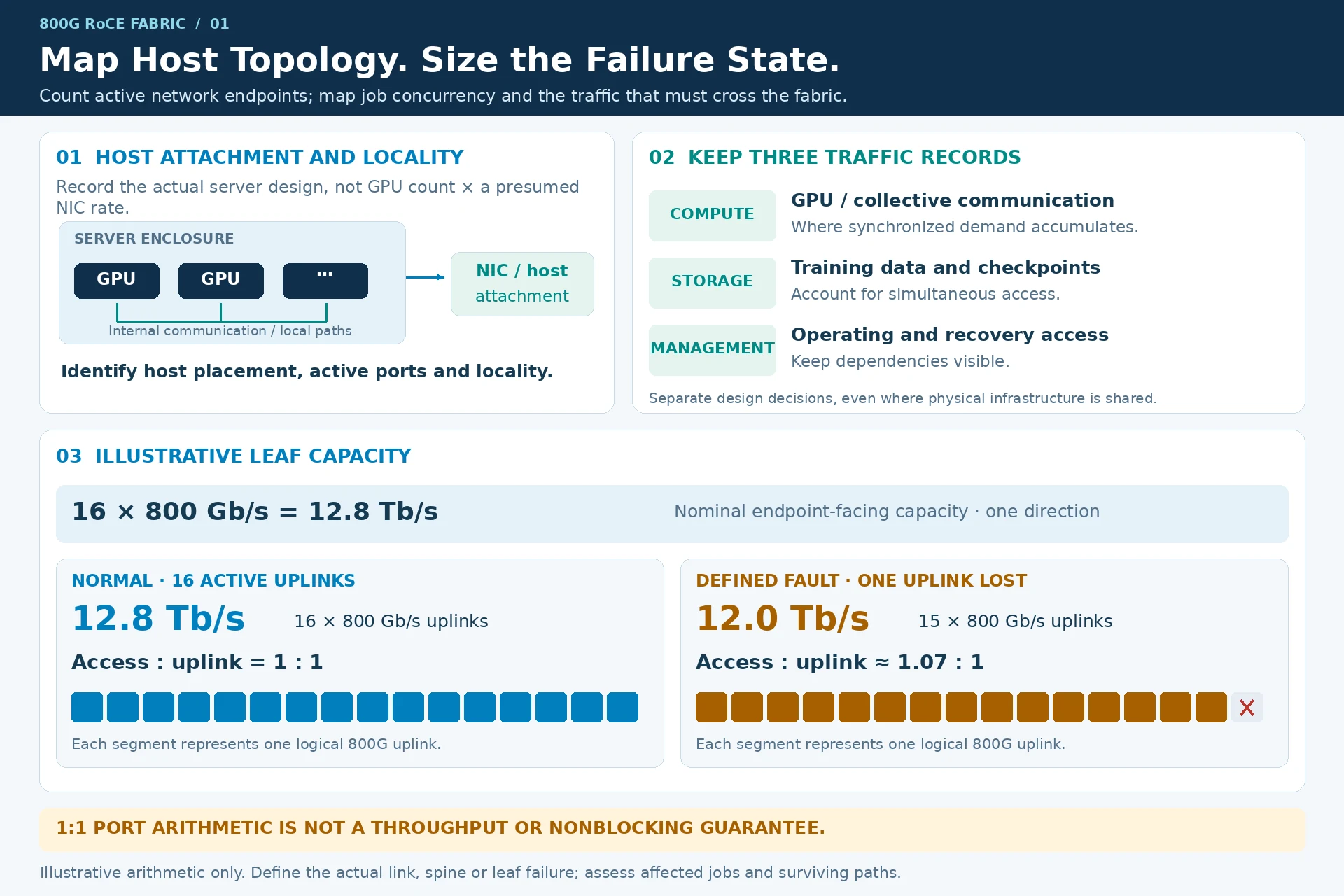
Record the server platform, GPU and adapter arrangement, host-interface placement and intended application transport. Identify which traffic stays inside a server and which crosses the fabric. Keep compute communication, storage access and management as separate design decisions, even when some share physical infrastructure.
Count active network endpoints rather than multiplying GPU quantity by a presumed adapter rate. The actual server design determines attachment and locality.
State the capacity assumption
Build the endpoint, leaf and spine port schedule together. For an illustrative leaf, sixteen 800G endpoint links provide 12.8 Tb/s of nominal access capacity. Sixteen equal-rate uplinks provide the same sum. This 1:1 arithmetic does not prove full application throughput or nonblocking behavior under every traffic pattern.
| Architectural question | Why it changes the design |
|---|---|
| Which jobs run concurrently? | Determines where synchronized demand can accumulate |
| How are endpoints distributed? | Changes cross-rack traffic and path requirements |
| What failure must be tolerated? | Determines surviving capacity and affected jobs |
| How will the cluster expand? | Reserves meaningful ports rather than arbitrary percentages |
Include both normal and degraded-state calculations. A fabric that meets normal traffic demand but cannot support the required failure condition has a different service capability than a resilient design.
Choose a coherent congestion policy
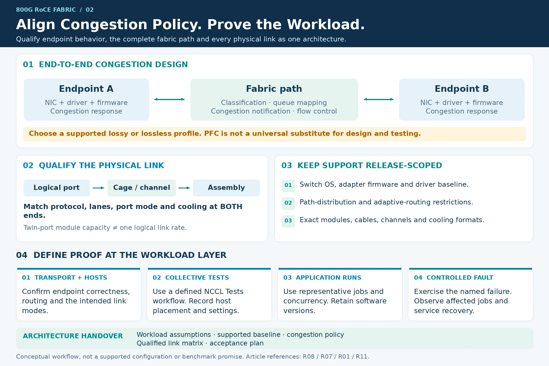
RoCE behavior depends on endpoint and network configuration together. Establish traffic classification, queue mapping, congestion notification and the applicable flow-control profile. NVIDIA documents both lossy and lossless RoCE profiles in specific Cumulus releases; PFC is therefore not a universal substitute for design and testing. R08
Path-distribution features also have platform and software restrictions. Do not assume that every Spectrum-based system offers identical adaptive-routing behavior. R07
Qualify every physical link
Record logical ports independently of physical cages. Match protocol, lane arrangement, port mode, supported assembly and cooling format at both ends. NVIDIA’s twin-port and cooling distinctions are particularly relevant when aggregate module capacity is confused with a single logical link rate. R01
The architecture should produce a qualified link matrix, not a loose list of devices carrying similar speed labels.
Define proof at the workload layer
Start with transport and endpoint correctness, then specify representative collective-communication tests and application runs. NCCL Tests can support a defined validation workflow, but test settings, host placement and software versions must accompany results. A benchmark number without those conditions is not a transferable performance promise. R11
Release the architecture with its workload assumptions, supported component baseline, congestion policy and acceptance plan. Use the separate deployment checklist to execute configuration and rollout. The architecture’s purpose is to explain why these decisions belong together.
Engineering illustrations
These figures illustrate the design concepts discussed here. They are not measured results, certified configurations or a supplied-equipment list.
Related reading
- Commissioning an 800G RoCE Fabric: A Layered Acceptance Plan
- AI Ethernet Fabric Design: From GPU Traffic to a Qualified BOM
- Why More Bandwidth Alone Will Not Fix a RoCE Fabric