
Network engineering
Campus Fiber Infrastructure: Design Between Buildings, Not Just Between Ports
Design interbuilding campus fiber with route diversity, service boundaries, fiber allocation and maintainable documentation.
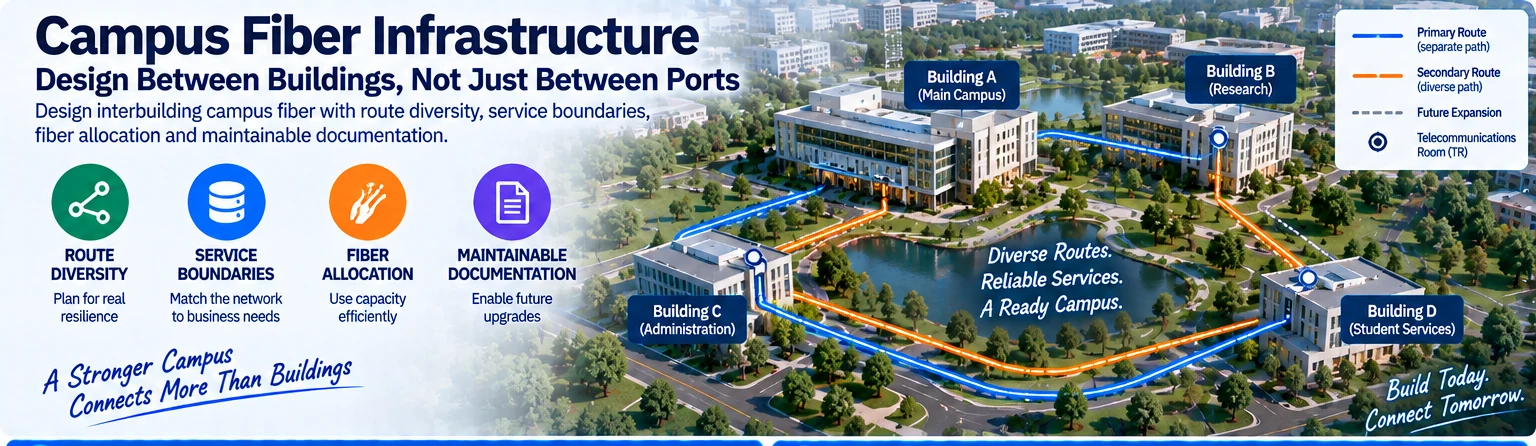
Interbuilding fiber is a long-lived infrastructure decision. Switches and optical modules may change several times during its service life, while civil routes and termination locations remain difficult to alter. Plan the campus pathway around service continuity, future access and documented fiber allocation before selecting the first set of optics.
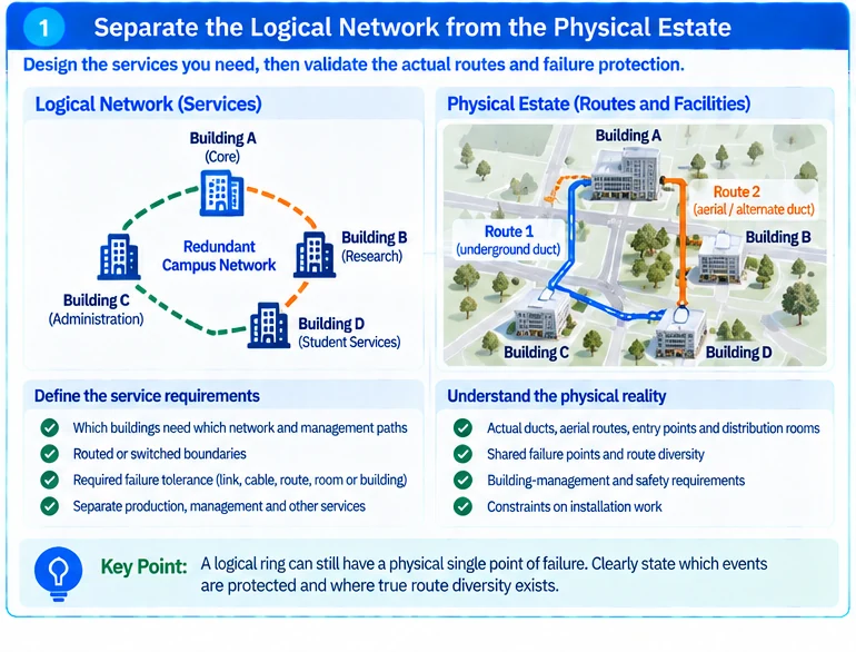
Separate the logical network from the physical estate
Draw the network services between buildings, then draw the actual ducts, aerial routes, entry points and distribution rooms. These drawings answer different questions. A logical ring may still contain a physical single point of failure if several segments share one trench.
Identify the failures the project must tolerate: one fiber, one cable, one route, one room or one building. Avoid describing a design as redundant without naming the protected event.
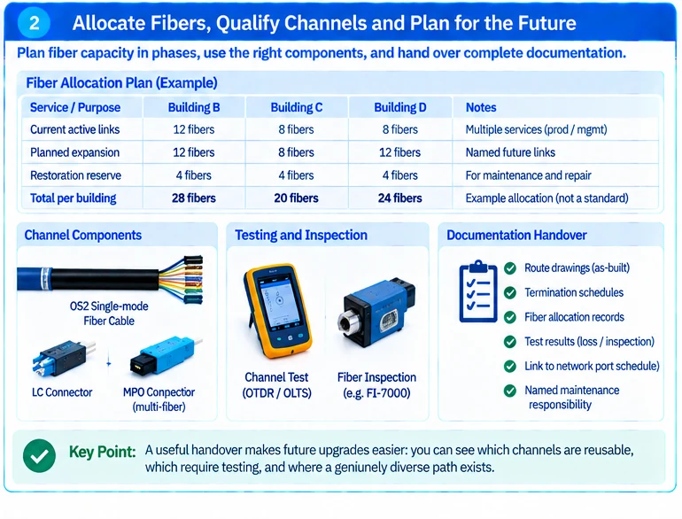
Allocate fibers against defined phases
Create a schedule for current links, the next approved expansion and restoration use. Specify how fibers are grouped and terminated so that future work does not require technicians to disturb unrelated services.
An illustrative campus with three remote buildings may use different routes and fiber allocations for each building. Reserving a fixed percentage everywhere can underprovide a growth building while wasting scarce termination space elsewhere. A named future link is a more useful planning unit than an unexplained reserve.
| Planning layer | Required output |
|---|---|
| Campus services | Which buildings need which network and management paths |
| Physical routes | Shared ducts, entries, rooms and access constraints |
| Fiber allocation | Active pairs or groups, expansion and restoration reserves |
| Optical qualification | Selected interfaces and complete channel limits |
| Maintenance | Ownership, identification, testing and repair access |
Resolve route conditions with the appropriate specialists
Outdoor exposure, building entry, fire compartments and installation protection require project-specific review. Use qualified cabling and facilities personnel and applicable local requirements. This network design article is not a substitute for construction approval or electrical and building-safety review.
At the network layer, choose routed or switched boundaries deliberately. Campus design guidance can inform service distribution and failure isolation, but should be adapted to the site’s actual buildings and operating model. R45
Qualify installed channels, including patching
Select fiber and connectors for the intended optical application and include intermediate connections in the channel budget. Record polarity and mapping for multi-fiber arrangements. A spare route is useful only if its fiber mapping and termination are known. R42
Retain inspection and channel-test results against stable link identifiers. Cleaning and inspection are part of connector-quality control, not a substitute for verifying the required end-to-end optical limits. R17
Hand over an infrastructure record
Deliver route drawings, termination schedules, fiber allocation, measured results and named maintenance responsibility. Link that record to the network port schedule, but do not replace it with one.
The result should make future upgrades easier to evaluate: an engineer can determine which channels are reusable, which require testing and where a genuinely diverse path exists. That is a stronger outcome than installing a high fiber count without a service and maintenance plan.
Engineering illustrations
These figures illustrate the design concepts discussed here. They are not measured results, certified configurations or a supplied-equipment list.
Related reading
- SFP-10G-ZR Qualification: Check Both Loss Margin and Receiver Overload
- Building Backbone Cabling: Capacity, Route Resilience and Service Access