
AI Ethernet · RoCE
AI Ethernet Fabric Design: From GPU Traffic to a Qualified BOM
Plan an AI Ethernet fabric around workload traffic, host interfaces, congestion behavior, link capacity and a testable bill of materials.
先明确这次评估需要做的决定
AI 以太网项目先把负载与现有设备整理成端口清单,再选模块。每条记录写清两端设备、目标链路模式和实际走线路径,并把已确认料号与工程待决项分开。产品经理可用下表讨论产品组合;项目经理可据此分派缺项。下方原有设计方法与公开部署案例继续作为详细参考。
四个料号,两类不同的链路
下表是主要的 100G / 400G 采购对照。正文后面的扩展清单还讨论了另一款 200G 模块;它的通道信号不同,不能只因标称速率相同就替代 200G 分支链路的端点。
| 目录项 / 型号 | 订货号 | 采购对象 | 选型条件 |
|---|---|---|---|
| 7599 · MMA1B00-C100D | 980-9I149-00CS00 | 100GbE QSFP28 SR4,4 × 25G,MPO/UPC | 100G 模式下 OM4 最远 100 m、OM3 最远 70 m;40G 距离另列。规格 · 订货信息 |
| 7620 · MMA4Z00-NS400-T | 980-9I51S-F4NS00 | 400GbE 单端口平顶 OSFP,MPO-12/APC | 4 × 100G PAM4,OM4 最远 50 m、OM3 最远 30 m;核对具体网卡接口笼与散热条件。规格 · OPN |
| 7672 · MFP7E10-N003 | 980-9I73U-000003 | 3 m 无源多模直连交叉光纤 | 四通道 MPO/APC 对四通道 MPO/APC。 |
| 7638 · MFP7E20-N003 | 980-9I571-00N003 | 3 m 无源多模 1:2 分支交叉光纤 | 四通道 MPO/APC 分成两个双通道 MPO/APC 支路。 |
光纤拓扑依据:NVIDIA 光纤表;光纤数字料号依据:固件参考表。这些资料用于识别部件;实际资格核验仍针对具体主机和固件。表中的 UPC 100G 模块不能与上述 APC 光纤直接配接。
一条逻辑链路一行
示例中的设备均为虚构。DEMO-01 演示一份字段齐全的 100G SR4 规划请求,仍列有负责人和待完成的支持核对;DEMO-02 演示信息不完整的 400G 请求。两者均不是实测配置或采购指令。分支链路分别填写 A、B 行,并保留相同父端口编号。
物理链路问题进入光模块与线缆核对表,主机问题进入网卡核对表。可直接提交已有端口表或 BOM,数量尚未确定可留待确认。
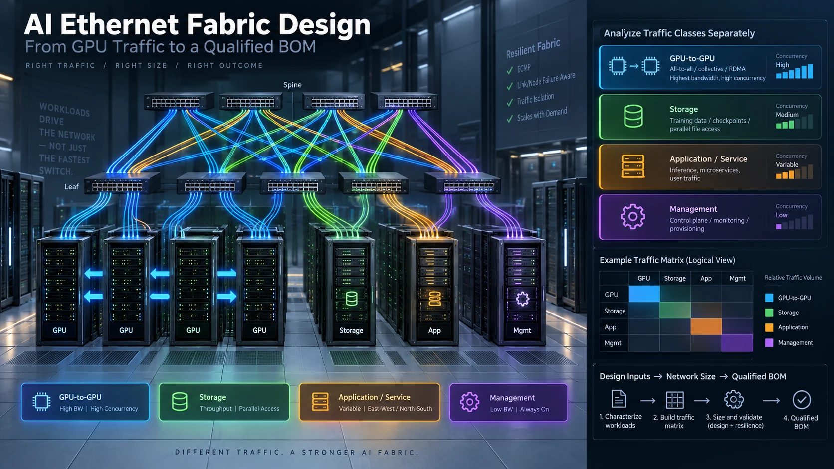
An AI Ethernet fabric should be designed around the communication that delays the workload, not around the fastest switch in the catalogue. The starting point is a traffic model: which servers exchange data, how many communicate at once, and what happens to the job when one path becomes unavailable. Switches, adapters and interconnects are then selected as a system.
This solution applies to a new GPU cluster or a controlled expansion. It describes an engineering method, not a prequalified configuration for an unspecified server.
Public NVIDIA Ethernet deployments: lessons for a 100–400G sourcing plan
The examples below are third-party public deployments. They provide context for the architecture and installation questions in this guide; they are not SwitchInfra delivery references or a bill of materials for the modules listed below.
xAI Colossus: qualify the fabric and its endpoints together
In its October 2024 report on xAI’s Colossus, NVIDIA identifies a Spectrum-X Ethernet deployment pairing Spectrum SN5600 switches with BlueField-3 SuperNICs. NVIDIA’s deployment announcement.
For a sourcing team, the useful connection is the system-level choice: identify the fabric platform, endpoint interface and software baseline before selecting individual link components. This case does not establish that the ConnectX-7 OSFP module, or any specific optical OPN below, was used at Colossus. Apply the same planning discipline to the buyer’s actual ports and supported link modes.
GMO GPU Cloud: include the installation procedure with the 400G parts list
GMO’s November 2024 launch announcement documents H200 GPUs and Spectrum-X for its GPU cloud. In a separate November 2025 engineering interview, the deployment team describes 400Gbps interconnect cables and cleaning and camera inspection of connector ends before connection. GMO launch announcement · GMO engineering interview, Japanese original.
For a buyer, this makes the cable schedule and inspection procedure part of the sourcing package. Record the actual route, connector ends, polarity, cleaning procedure and acceptance evidence. These are procurement requirements proposed here; the public interview does not disclose the installed optics’ OPNs, connector polish, fiber count or complete cable mapping. The different dated publications must not be assembled into an invented complete BOM.
Turn the deployment lessons into an RFQ
Use the architecture and installation questions together: first identify both host ports and the intended fabric, then qualify each module and jumper against that link. The 100–400G shortlist later in this guide follows original product specifications rather than assuming it is either case’s deployed hardware. Keep the UPC/APC, straight-crossover/breakout and acceptance conditions attached to each proposed line item.
For the next step, use the optics and cable selection checklist with the adapter selection guide, then prepare the link-by-link RFQ below. A project’s workload and fault tests must establish its own results; public deployment outcomes are not a performance promise for a purchased module.
Separate the networks before sizing them
Build four traffic records: GPU-to-GPU communication, storage access, application or service traffic, and management. Shared infrastructure may be appropriate, but the design must account for simultaneous demand and explain the isolation policy. A storage checkpoint that coincides with a collective operation can expose a bottleneck that average interface utilization does not show.
For each record, identify the endpoint interfaces, expected concurrency, cross-rack paths and required behavior during a fault. Map adapters to the actual server topology. GPU count alone does not establish the required number of network ports.
Turn the traffic matrix into a port budget
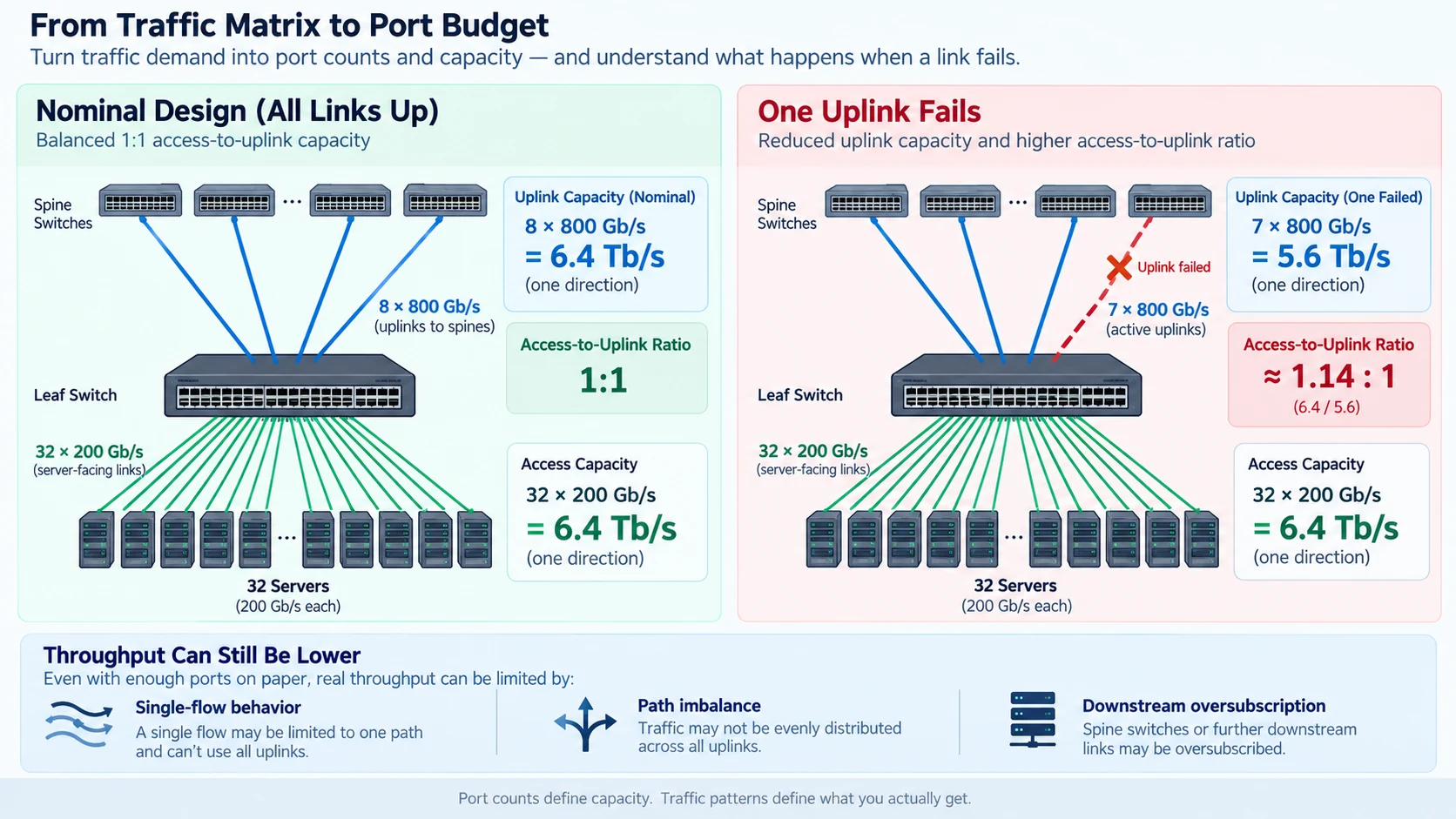
Calculate nominal capacity separately for server-facing links and uplinks. As an illustrative example, 32 access links at 200 Gb/s offer 6.4 Tb/s in one direction. Eight 800 Gb/s uplinks offer the same nominal total. Losing one uplink leaves 5.6 Tb/s, increasing the nominal access-to-uplink ratio from 1:1 to approximately 1.14:1.
These are planning calculations, not throughput results. The useful question is whether the remaining paths can carry the traffic that must survive the fault. A single flow, uneven path distribution or an oversubscribed downstream stage can still limit performance.
Qualify the platform and congestion policy together
Choose a switch operating-system release, adapter firmware and driver baseline before approving the hardware list. Where the design relies on a particular adaptive-routing capability, verify its documented hardware, interface and release constraints. Do not assume every Spectrum generation implements the same behavior. R07
For RoCE, define traffic classification, queue mapping, congestion notification and endpoint response across the path. NVIDIA’s Cumulus documentation distinguishes lossless and lossy RoCE configurations; a PFC-based lossless profile is not a reason to enable pause behavior indiscriminately on all traffic. The operational test must show that the chosen profile works for the intended workload. R08
Make every BOM line serve a connection
| Design object | What the implementation record must contain |
|---|---|
| Host attachment | Server, slot, adapter variant, port and software baseline |
| Access link | Both endpoints, target mode, module or cable assembly, routed length |
| Fabric link | Leaf and spine logical ports, capacity and failure-group assignment |
| Optical channel | Fiber type, connector and polarity, panels and measured loss |
| Operations | Management access, power feeds, approved spares and recovery procedure |
Record physical cages and logical ports separately. Twin-port modules and host cooling arrangements can change both component quantities and compatibility. A module described only as “800G OSFP” is not a complete link specification. R01
Shortlisting NVIDIA 100–400G optics and fiber jumpers
Once the traffic model has produced a port schedule, scope the optical BOM by matching each link to a documented module and cable pair. The list below summarises four NVIDIA items in the 100–400G multimode range. Final acceptance depends on the exact hosts, adapters, switch ports, software baseline, link mode and installed channel.
- 100GbE — MMA1B00-C100D: QSFP28 MMF SR4 with an MPO UPC optical interface. Four 25Gb/s electrical inputs drive four optical channels at 850nm; the optical interface has four fibers in each direction. At 100Gb/s, NVIDIA specifies up to 100m on OM4 or 70m on OM3. The separate 40GbE mode supports up to 100m on OM3; that figure must not be used as the 100GbE OM3 reach. NVIDIA product specifications.
- 200GbE — MMA1T00-VS: QSFP56 SR4, four 50Gb/s PAM4 channels at 850nm, with a male MPO-12 UPC receptacle and four optical fibers in each direction. The specified reach at 200Gb/s is up to 100m OM4 or 70m OM3. A matching cage does not establish support on a particular host and firmware. NVIDIA product specifications.
- 400GbE — MMA4Z00-NS400-T: the Ethernet -T variant is a single-port OSFP SR4 module with four 100G-PAM4 channels, 850nm optics and an MPO-12/APC interface. NVIDIA specifies up to 50m OM4 or 30m OM3; its 50m description assumes two optical patch panels. Its flat-top shell uses the heatsink on a ConnectX-7 OSFP cage. Optical specifications and shell design.
- Straight crossover cable — MFP7E10-N003: this exact OPN is a 3m multimode straight crossover cable, with a four-channel MPO/APC connection at each end. The MFP7E10 family also has separate OPNs for 5, 7, 10, 15, 20, 30 and 50m. The distinct MFP7E20 family, including the separately listed MFP7E20-N003, provides the 1:2 splitter/breakout assembly, from one four-channel MPO/APC to two two-channel MPO/APC connections. It is not the topology of MFP7E10-N003. NVIDIA recommended cable OPNs.
Keep the host, connector and channel conditions with the model
The MMA4Z00-NS400-T overview places this flat-top module in ConnectX-7 OSFP adapters. It states that the described single-port OSFP is not used in switch ports, and that BlueField-3 uses QSFP112 devices. These conditions concern the documented products and deployment; they do not establish the compatibility of an arbitrary OSFP or QSFP112 module. Keep the -T Ethernet part distinct from a similarly named product without that suffix.
For the documented 1:2 MFP7E20 arrangement, a split end activates two channels in the 400G module, giving a 200GbE link. That two-channel 100G-PAM4 mode is different from the MMA1T00-VS four-channel 50G-PAM4 mode. Do not infer that the modules interoperate because both links are labelled 200G. The overview also requires the two optical connections in its described Twin-port 2×400G arrangement to use the same cable type: both straight crossover or both splitter, never one of each. Check the exact endpoint variants and port mapping against the NVIDIA connectivity overview.
The 100G and 200G modules listed here use UPC interfaces; the listed 400G module and MFP7E10/MFP7E20 cables use APC. An APC face must not be mated to a UPC face. A shared MPO-12 connector name does not remove that condition. Optical channels, transmit/receive fibers and connector positions must be recorded separately; a four-channel description does not mean four total fibers for both directions. A breakout cable routes channel groups and does not convert wavelength or signal format, or act as a passive optical-power divider.
What to send for an RFQ
Provide the following for each link:
- Hosts and software: exact server or switch, adapter variant, slot, port/cage identifier, firmware, driver and switch-OS baseline.
- Endpoints and mode: both module OPNs, target speed and protocol, host-to-switch or switch-to-switch path, and any supported breakout mode and branch mapping.
- Optical channel: UPC/APC faces at both ends, OM3/OM4 medium, active transmit/receive fibers, polarity, routed length, panel positions and measured or planned loss budget.
- Cable assembly: exact OPN and length, including whether the link uses an MFP7E10 straight crossover or an MFP7E20 1:2 assembly. Record both connections for the documented twin-port arrangement.
- Commercial requirements: quantities and spares, destination country/site, required arrival date and agreed acceptance tests.
Send the link list and BOM through SwitchInfra’s BOM / RFQ form. Include the exact endpoint models, quantities, cable lengths, delivery country and required arrival date. Ask for confirmation of availability, pricing, lead time and acceptance conditions for that project. For questions before preparing the BOM, use Contact Us.
Recognition and negotiated speed are the first checks. Qualification also needs the installed channel’s polarity/loss results, diagnostics and error counters under agreed traffic, tests of every intended branch, and the application’s agreed load and fault tests. Retain those results with the exact hardware and software configuration. The reach figures above are manufacturer specifications, not a measurement of the installed link.
This shortlist does not confirm inventory, price, lead time, warranty, a customer RFQ or qualification on an unspecified host. Those items remain to be checked for the actual project.
Stage the fabric in three gates
First, commission a representative host-to-switch path and verify recognition, negotiated mode and error counters. Second, exercise the multi-path fabric with controlled traffic, including the busiest expected communication pattern. Third, run the intended application or collective workload at increasing concurrency and repeat the agreed tests after a controlled fault.
Retain useful throughput, completion time, tail behavior and relevant congestion indicators with the configuration. Compare runs only when the workload and measurement conditions are equivalent.
The project is ready for a sourcing review when it has a topology, port schedule, qualified link list, failure-state capacity calculation and acceptance plan. That package makes the proposed fabric explainable before large equipment orders are placed.
Engineering illustrations
These figures illustrate the design concepts discussed here. They are not measured results, certified configurations or a supplied-equipment list.
Related reading
- ConnectX and BlueField Selection: Host Fit, Protocol and Offload Requirements
- Optics and Cable Selection Checklist: Qualify Both Endpoints and the Channel
- Link-Up Is Only the First Test of an AI Network