
InfiniBand · NDR
NDR 400G InfiniBand Design: Endpoint Counts, Topology and Acceptance
Size an NDR InfiniBand cluster from HCA ports and topology, then qualify cables, fabric management and representative workload behavior.
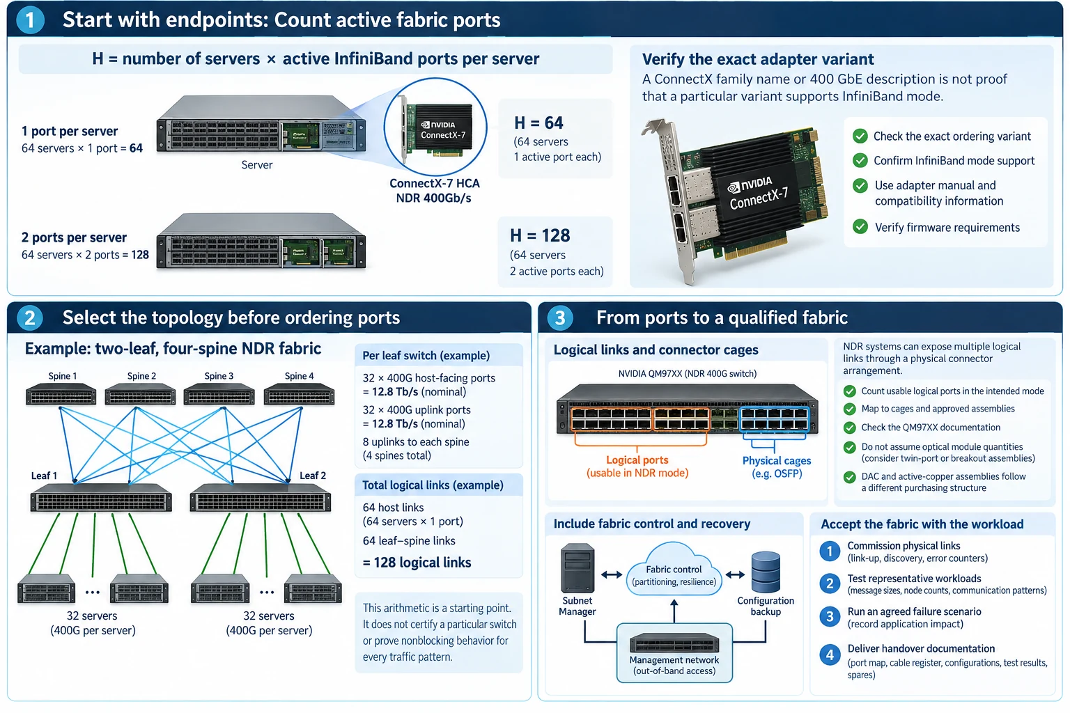
An NDR cluster starts with an endpoint inventory, not a switch count. The same number of servers can require very different fabrics when they contain different HCA counts, active ports or rail assignments. A defensible design connects that inventory to a topology, an exact interconnect list and a workload acceptance plan.
Use this approach for a new InfiniBand compute network or a bounded expansion. Storage, external services and out-of-band recovery access should be described separately, even when some infrastructure is shared.
Count active fabric ports
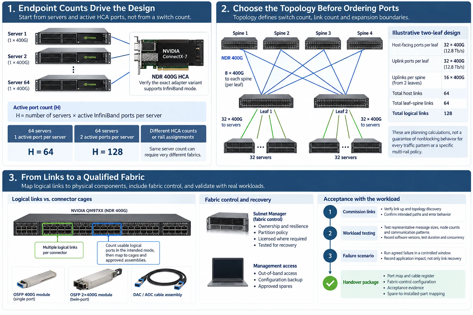
Let H equal the number of servers multiplied by the active InfiniBand ports per server. For an illustrative 64-server cluster with one active 400 Gb/s HCA port per server, H is 64. Two active ports per server would make H 128; it would not automatically define how those ports should be assigned to rails or switches.
Verify that each exact adapter ordering variant supports the required InfiniBand mode. A ConnectX family name or a 400 GbE description is not proof that a particular Ethernet-oriented variant is an appropriate HCA for this fabric. Use the adapter manual and the applicable compatibility information. R51R06
Select the topology before ordering ports
A single switching stage can reduce component count when the endpoint and resilience requirements fit it. A two-stage leaf–spine fabric consumes additional switch ports and links but can create a clearer expansion boundary.
Consider an illustrative two-leaf arrangement with 32 host-facing 400G ports and 32 uplink ports per leaf. Each leaf has 12.8 Tb/s of nominal access capacity and the same nominal uplink capacity. If those uplinks are spread across four spines, each leaf uses eight links to each spine. Each spine then receives 16 leaf-facing links from the two leaves. The design needs 64 host links and 64 leaf–spine links: 128 logical links in total.
This arithmetic does not certify a particular switch, prove nonblocking behavior for every traffic pattern or account for a selected multi-rail policy. It is a transparent starting point for reviewing the topology.
Keep logical links separate from connector cages
NDR switch systems can expose multiple logical links through a physical connector arrangement. Count usable logical ports in the intended mode, then map them to cages and approved assemblies. The QM97XX documentation is the reference for the exact system rather than a faceplate photograph or aggregate module label. R52
Do not estimate optical-module quantities by multiplying every logical link by two without checking the implementation. A conventional single-port optical link uses a module at each end; twin-port modules and breakout assemblies require channel-level counting. DAC and active-copper assemblies follow a different purchasing structure.
Include fabric control and recovery
| Layer | Design decision |
|---|---|
| Hosts | HCA identity, PCIe placement, active port and rail mapping |
| Switching | Leaf/spine roles, usable ports and supported operating modes |
| Fabric control | Subnet-management ownership, resilience and partition policy |
| Interconnect | Exact assemblies or modules, route and channel mapping |
| Recovery | Management access, configuration backup and approved spares |
List management appliances and software entitlements separately. A connected management port does not establish that the fabric-control service has been configured, licensed where required, or tested for recovery.
Accept the fabric with the workload
Commission physical links first. Confirm topology discovery, intended paths and error behavior before running large jobs. Then test representative message sizes, node counts and communication patterns. Save the software versions, test duration and concurrency with every result.
Run the agreed failure scenario in a controlled window and record application impact, not only link recovery. The handover should include the port map, cable register, fabric-control configuration, acceptance evidence and spare-to-installed-part mapping. These are the records needed to expand the cluster without rediscovering its assumptions.
Engineering illustrations
These figures illustrate the design concepts discussed here. They are not measured results, certified configurations or a supplied-equipment list.
Related reading
- NVIDIA Switch Selection Worksheet: Logical Ports, Cages and Rack Requirements
- Optics and Cable Selection Checklist: Qualify Both Endpoints and the Channel
- Link-Up Is Only the First Test of an AI Network