
Network engineering
Optical Networking Solutions: Separate Client Links, Channels and Transport Systems
Select optical networking architectures by service boundary, reach, wavelength use, channel constraints and operational ownership.

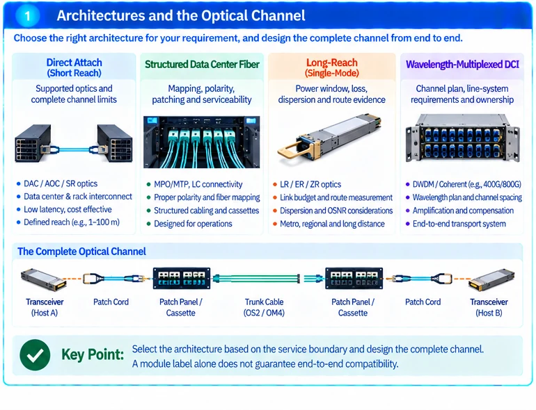
Optical networking covers several different engineering tasks. A short data-center channel, a campus backbone and a wavelength-multiplexed inter-site system should not be selected from one generic list of transceivers. Define the service boundary and physical path before comparing optical products.
Choose the appropriate architecture
| Requirement | Design focus |
|---|---|
| Direct equipment-to-equipment link | Supported endpoint optics and complete channel limits |
| Structured data-center fiber | Mapping, polarity, patching and serviceability |
| Long-reach single-mode connection | Power window, loss, dispersion and route evidence |
| Wavelength-multiplexed DCI | Channel plan, line-system requirements and ownership |
Use the dedicated fiber-cabling, long-reach and DWDM-PAM4 solutions for those respective scopes. They address different systems rather than interchangeable distance grades of the same module.
Keep the vocabulary in separate layers
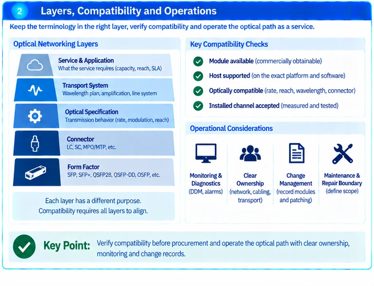
A form factor describes a mechanical/electrical implementation. A connector describes part of the physical mating interface. An optical specification defines transmission behavior under stated conditions. A wavelength plan and line system describe how signals are carried across a broader route.
None of these labels alone establishes end-to-end compatibility. Vendor transceiver documentation contains different implementations at the same advertised rate, reinforcing the need to identify exact parts and intended applications. R18R25
Design the complete channel
Record both hosts, modules, fiber paths and intermediate components. For multi-fiber systems, include active fiber positions and polarity. A cassette or trunk can organize connections without converting their optical standards. R42
For managed transport, include every required active and passive function and the team responsible for it. Some DWDM-PAM4 products specify associated amplification or compensation conditions; those belong to the documented implementation and cannot be assumed away. R41
Define evidence before procurement
Collect route length and loss information, endpoint support records and the operating constraints of the candidate optics. Identify missing information as an engineering dependency rather than filling the gap with a nominal reach label.
An illustrative procurement comparison should distinguish “module available,” “host supported,” “optically compatible” and “installed channel accepted.” These are different stages of confidence, not synonyms.
Operate the optical path as a service
Keep diagnostics and channel test results tied to stable link identifiers. Define alarm ownership and the repair boundary between network, cabling and transport teams. Record changes to patching or modules so that old acceptance evidence is not applied to a different path.
For scoping, provide endpoint models, required rate, route measurements, fiber and connector details, and any existing transport system. This information makes an optical solution reviewable before ordering rather than leaving compatibility to installation day.
Engineering illustrations
These figures illustrate the design concepts discussed here. They are not measured results, certified configurations or a supplied-equipment list.
Related reading
- DWDM-PAM4 DCI Design: Qualify the Optical System, Not Just the Pluggable
- Long-Reach 10G Fiber Design: Loss Budget, Receiver Limits and Acceptance