
Network engineering
Video Surveillance Networking: Plan the Complete Camera-to-Recording Service
Design surveillance connectivity around camera streams, PoE, recording and viewing paths, security boundaries and recovery evidence.
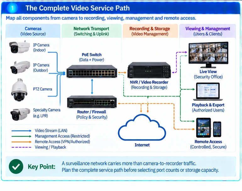
A surveillance network carries more than camera-to-recorder traffic. Live viewing, remote access, playback, export and administration can share links and processing resources. Design the complete service path before selecting switch port counts or storage capacity.
Map the video service
Identify cameras, recording systems, viewing stations and management services. Record where streams are generated, stored and retrieved. Define the expected recording schedule and the number of concurrent viewers or playback sessions.
Keep network design separate from the organization’s decisions about lawful recording, retention and access. Those requirements need their own accountable review; a connectivity solution does not establish compliance.
Divide the engineering work
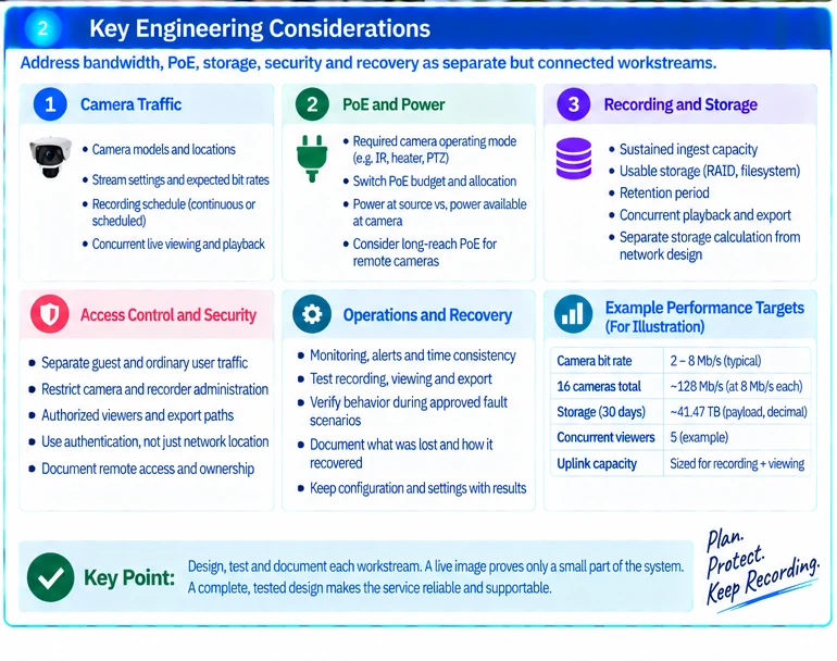
| Workstream | Required output |
|---|---|
| Camera traffic | Stream settings, expected rates and concurrency assumptions |
| Network transport | Port map, uplink capacity and defined failure behavior |
| Endpoint power | Required camera modes and available PoE allocation |
| Recording and retrieval | Ingest, usable storage, retention and playback requirements |
| Access control | Authorized viewers, administrators and export paths |
| Operations | Monitoring, time consistency and recovery procedures |
Use the small-business video solution for a worked bandwidth and storage calculation. Larger or distributed systems require the same distinctions, with additional attention to shared paths and remote-site dependencies.
Check power independently of data
Some camera functions change power requirements. Verify the required operating mode and the switch’s documented budget, including any intended power-failure scenario. Power at the source and power available to the endpoint are different quantities. R32
For remote cameras, use the long-reach PoE planning workflow to compare data and power architectures. Do not assume that a longer cable preserves every data-rate and power requirement.
Control the management and viewing paths
Restrict camera and recorder administration to approved operators. Separate guest or ordinary user traffic from infrastructure interfaces and define which viewing services may cross the boundary. Application authorization remains necessary even within a segmented network. R35
Document remote-access ownership and recovery arrangements. An exposed management interface is not an acceptable substitute for a controlled support path.
Accept recording, retrieval and recovery
Test sustained recording, representative simultaneous viewing, playback and permitted export. Verify timestamps and monitoring. Trigger only approved fault scenarios and document what video or service was lost and how operation resumed.
Retain the actual camera settings, network configuration and storage assumptions with the results. A live image on one screen proves only a narrow part of the system.
For project scoping, provide camera models, stream settings, locations, recording and retention requirements, viewing patterns and existing infrastructure. This supports a complete camera-to-recording design rather than an equipment list that leaves the critical bottleneck elsewhere.
Engineering illustrations
These figures illustrate the design concepts discussed here. They are not measured results, certified configurations or a supplied-equipment list.
Related reading
- Small-Business Video Networks: Size Camera Traffic, PoE and Recording Storage
- Long-Reach PoE Design: Separate the Data Path from the Power Problem