The landscape of enterprise data centers is undergoing a rapid transformation driven by the exponential growth of artificial intelligence (AI) workloads, the demand for hyperscale cloud computing, and the proliferation of high-bandwidth applications. As organizations look to expand their infrastructure to meet these new demands, the focus has shifted from simple capacity expansion to the creation of high-density 400G network architectures. A standard 100G backbone is often insufficient for the bandwidth-hungry requirements of modern AI training clusters and high-performance computing (HPC). Consequently, deploying a 400G network is no longer a luxury but a strategic necessity for competitive IT operations.
However, moving to 400G speeds introduces significant complexity, particularly when managing high-density deployments. High density in this context refers to maximizing port counts within limited rack space while maintaining optimal power efficiency and thermal management. This guide is designed to help network architects, IT buyers, and data center engineers navigate the critical steps required to design a robust, scalable, and energy-efficient 400G network. By understanding the architectural implications, hardware selection criteria, and operational best practices, you can build a data center design that not only meets current bandwidth requirements but is future-proofed against the next generation of 800G and beyond.
Understanding the Requirements for 400G High-Density Deployments
Before selecting any equipment, it is essential to understand the specific constraints that differentiate a 400G network from its 100G predecessors. The transition to 400G is not merely about increasing speed; it is about managing the physical layer constraints that come with higher data rates.
Bandwidth and Latency Considerations
In a 400G network environment, bandwidth is paramount, but latency remains a critical performance metric, especially for applications relying on low-latency interconnects like InfiniBand or RoCE (RDMA over Converged Ethernet). When designing a high-density 400G switch, engineers must consider how packet processing impacts jitter and round-trip time (RTT). High-density ports often mean higher switching silicon load. If the switch cannot process 400Gbps ingress and egress lines efficiently, congestion will occur at the aggregate level, leading to packet loss and degraded application performance. Therefore, selecting a 400G switch with robust forwarding capabilities is the first step in data center design.
Power and Thermal Constraints
High density directly correlates to power density. A rack filled with 400G ports generates significantly more heat than 100G deployments. The power consumption of a switch chassis can increase by 50% or more when moving from 100G QSFP28 interfaces to 400G QSFP56 interfaces, even if the active power draw per port is similar, the aggregate load grows. In high-density scenarios, where every U of rack space is utilized to maximize port density, standard air conditioning systems may struggle to maintain the necessary PUE (Power Usage Effectiveness) targets. This necessitates a redesign of the cooling strategy, often requiring liquid cooling capabilities for the chassis or advanced hot/cold aisle containment.
Form Factor and Port Density
Traditional 400G switches often utilized 10U chassis sizes for 48-port 400G capabilities. However, modern designs favor compactness. High density is often achieved through smaller form factors, such as 2U or 3U chassis with 48x 400G ports. This consolidation allows operators to fit more aggregation bandwidth into a smaller footprint. When designing the physical layout, you must account for the clearance required for fan trays, power modules, and cable management. 400G DAC (Direct Attach Copper) cables are generally thicker than 100G versions due to the increased number of signal lanes (Copper pairs vs. optical fibers). If you are running high density cabling in standard 48-port racks, the cable path must be managed carefully to avoid bending radius issues, which can lead to signal degradation.
Architectural Principles for Scalable 400G Networks
The topology of your 400G network is the foundation of its scalability. As you move toward high density, the topology must minimize hop counts to reduce latency and prevent bottlenecks.
The Fat-Tree Topology
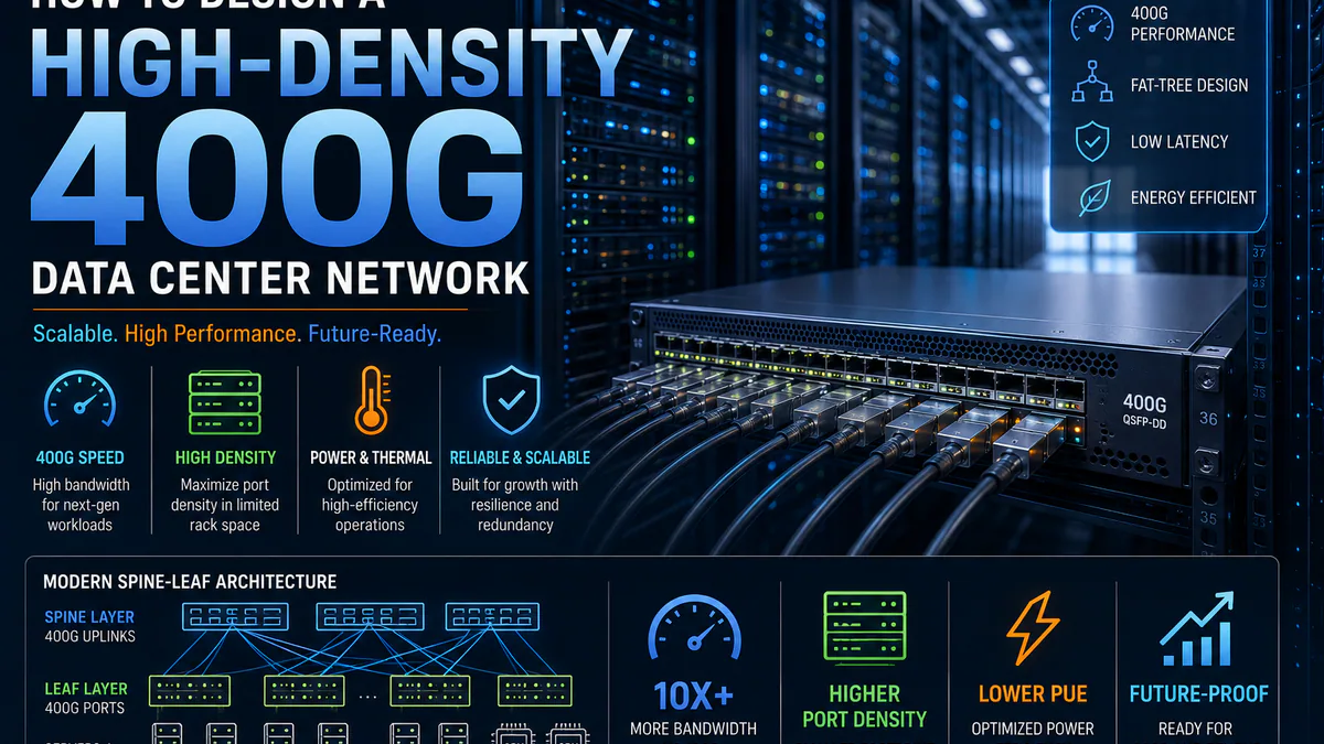
The Clos network or Fat-Tree topology remains the industry standard for data center spine-leaf architectures. In a 400G context, this means deploying 400G QSFP56 modules on spine switches. A high-density design typically utilizes a multi-tiered approach:
- Spine Layer: Utilizes 400G QSFP-DD uplink modules to connect to the core. These switches typically have lower port density of uplinks but higher backplane capacity.
- Leaf Layer: These are the access switches where the 400G ports terminate. For high density, these often feature 48x 400G QSFP56 ports, allowing a single rack to connect to an entire 400G spine layer.
Cabling Strategies for High Density
Cabling is a major factor in high-density data center design. The choice between DAC (Direct Attach Copper) and AOC (Active Optical Cable) significantly impacts port density and cable management.
- DAC: 400G DAC cables are the most cost-effective solution for short distances within the same rack or between adjacent racks. However, high-density 400G DAC cables are often thicker, requiring careful routing. When you have to run hundreds of these cables, the “magma” of copper can clog the rack.
- AOC: 400G AOC cables are thinner but consume more power due to the transceiver active electronics. In high-density environments, power consumption is a primary constraint. However, for longer inter-rack links, AOC is preferred to reduce EMI and simplify cable management.
Network Redundancy
A 400G network is a critical part of your data center. If a single switch fails in a 400G spine-leaf, you might lose a massive chunk of bandwidth. However, redundancy strategies must account for the physical density. In high-density racks, you might share power supplies between multiple switches to optimize space. This creates a “power sharing” risk. You must ensure that the failure of one power module doesn’t take down the entire leaf switch. Always use redundant power supplies in high-density 400G switches, and configure them with hot-swap capabilities to allow maintenance without downtime.
Hardware Selection: Choosing the Right 400G Switch
Selecting the hardware for your high-density 400G network involves careful evaluation of port density, performance, and compatibility with your existing ecosystem.
Evaluating Switch Port Density
When looking for 400G switches, the port count is a major specification. However, you must consider the type of ports available.
- All 400G QSFP56 Switches: These provide maximum flexibility, allowing you to use 400G uplinks, 400G server connections, or even bundle them for 200G/100G/40G use. High-density 32-port or 48-port 400G models can let a single rack handle immense bandwidth when cooling and power are planned correctly.
- Hybrid Ports: Some switches offer a mix of 400G and 100G ports. While versatile, this can limit high-density performance if the 400G ports are occupied by 100G traffic due to the need for aggregation. For a pure high-density 400G environment, a switch with 100% 400G ports is preferred.
Evaluating 400G Switch Performance
Key performance indicators include packet per second (PPS) handling and line rate forwarding.
- Line Rate Forwarding: Your 400G switch must operate at the full line rate. If you connect two 400G ports and the switch can only process 390Gbps, you will see a drop in throughput and potential congestion. High-density designs require switches that handle the aggregate load without dropping packets.
- ASIC Efficiency: The switching ASIC (Application-Specific Integrated Circuit) determines how efficiently the switch processes traffic. Modern 400G switches use advanced ASICs that allow for better thermal management and lower power consumption. This is crucial for high-density racks where cooling is already a challenge.
- OS Support: Ensure the switch runs a robust operating system like Comware or VOS, which can handle complex routing protocols like BGP, OSPF, and VRRP, essential for large-scale data center designs.
Choosing 400G QSFP56 Transceivers
The performance of your 400G switch is only as good as the transceivers you use.
- 400G QSFP-DD SR8: This module uses 8x 50G optical channels for distances up to 100 meters using MMF (Multimode Fiber). It is often used in high-density server racks to connect to short-range optical switches or for internal rack aggregation.
- 400G QSFP56 DAC: These are copper cables that terminate into QSFP56 form factors. They are essential for high-density server connectivity or short-distance inter-switch links.
- Compatibility: Always check compatibility lists. Using a 400G QSFP-DD DR4 (for long distance) in a rack designed for 100G might work, but the physical size of the 400G module is larger. Some 400G switches have larger cages, while others might require specific adapters. High-density 400G QSFP56 modules are designed to fit standard QSFP cages. If you are mixing 100G and 400G, you might need QSFP56-to-QSFP28 adapters, which can be a point of failure.
Procurement Considerations for 400G Data Center Design
For data center architects who need to balance high density with cost-effectiveness, the key is to evaluate switch platforms and optics as a complete system instead of buying them independently.
High-Density 400G Switches
High-density 400G switches usually stand out for compact form factors, dense QSFP56 or QSFP-DD port layouts, and non-blocking forwarding capacity. They allow teams to deploy aggregation or spine-leaf fabrics without increasing rack footprint. When evaluating these platforms, confirm thermal design, redundant power, fan direction, break-out support, and the operating system features needed for BGP, EVPN-VXLAN, telemetry, and automation.
Hybrid 100G/400G Designs
Some environments need 400G uplinks while retaining 100G server or storage connectivity. Hybrid designs can reduce migration cost, but they require careful breakout planning and capacity modeling. Validate whether the switch supports the required fan-out modes, optics combinations, and routing scale before finalizing the bill of materials.
400G QSFP56 Modules
Common 400G optical and copper choices include:
- 400G QSFP-DD SR8: For short-reach connectivity up to 100 meters.
- 400G QSFP56 DAC: For direct copper connections.
- 400G QSFP-DD DR4: For long-reach connectivity up to 400 meters. These modules are designed for high density and are compatible with a wide range of 400G switches. They support the necessary 400G QSFP56 form factor and are built to handle the high bandwidth demands of modern AI workloads.
Optimizing Cabling and Power for High-Density 400G
Even the best 400G switch cannot perform if the cabling infrastructure or power supply is inadequate. In high-density 400G deployments, the following factors must be addressed.
Managing 400G Cables in High Density
Cabling is a significant component of a high-density data center. 400G cables are thicker and have stricter bend radius requirements than 100G cables.
- Bend Radius: 400G QSFP-DD cables generally require a minimum bend radius of 10 times the cable diameter for DAC and 15 times for AOC. In high-density racks where cable management space is limited, this can be challenging. You must use cable managers or risers specifically designed to accommodate the thickness of 400G cables.
- Cable Management: To maintain high performance, cable management is critical. Loose or improperly routed 40 managers (a typo in the original text) 400G cables can cause physical strain on the transceivers, leading to link failures or performance degradation.