
Campus networks
What must an optical BOM capture across a campus ring with more than 20 distribution nodes?
Translate a university distribution project into route, pair and protection requirements before choosing optics.
A campus ring concentrates many fibers in a few critical rooms. The useful purchasing unit is a traceable end-to-end channel, with an explicit protection role, rather than an ODF connector count.
The short answer
Specify node and route identities, the splice-to-patch map, available fiber pairs and active port roles. A physical ring and a dense ODF do not establish service redundancy.
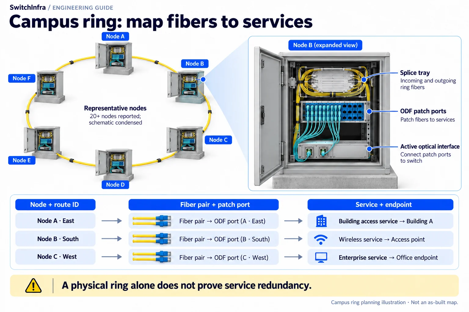
Map the route, fiber pair and ODF port to a service endpoint. A physical fiber ring alone does not establish service redundancy. Conceptual illustration; equipment shapes are illustrative.
Third-party project account · Independent analysis by SwitchInfra
Not a SwitchInfra deployment. Candidate equipment is proposed for comparable requirements.
20+ — reported backbone distribution nodes
Ring — reported campus backbone
NGF / FACT — reported distribution systems
Unknown — link speeds and optical PIDs
What the documented project tells us
CommScope describes a new-campus backbone using NGF and FACT fiber management, with FACT at more than 20 ring nodes. Its account brings campus, network-room and data-center fibers into common distribution management.
For a comparable campus, the design question is how to keep those physical connections intelligible as faculties, buildings and services grow. Optical reach matters, but an unidentified pair cannot be purchased or maintained reliably.
Topology — The supplier describes a campus ring backbone.
Nodes — More than 20 nodes use FACT distribution management.
Central rooms — NGF is described for the main campus access room.
Handoffs — The account separates splicing and patching operations.
Scope of the analysis: Public project analysis of a third-party supplier account. Not a SwitchInfra deployment or independent acceptance report. Every proposed rate and model below is a separate design exercise.
Work through the engineering choices
Start with the documented constraint, then state the conditions for the proposed equipment role.
Turn the ring drawing into individual channel records
The reported backbone has multiple distribution nodes.
Design exercise: Design exercise: one protected connection from a faculty building to a core room.
Give each physical route a separate identifier. Record its start and finish, intermediate distribution points, installed fiber grade, termination type and measured length. A line drawn around campus does not show whether two services share a conduit or building entrance.
Then assign equipment-facing ports to those routes. Separate working capacity, protection capacity and unallocated fibers. A closed physical ring may carry point-to-point services with no automatic restoration; define the intended switching or routing behavior before ordering duplicate optics.
Reconcile splice capacity with duplex service capacity
The project account describes separate splice and distribution management.
Design exercise: Design exercise: reconcile an incoming trunk against a proposed building handoff.
Follow the fiber through splice records, pigtails, adapters and jumpers to the far-end equipment. Count complete pairs, not individual termination positions. Product maximum capacity is a planning limit; it does not establish how many positions were installed or remain available.
A cassette or adapter change can alter the equipment-facing interface without changing the outside-plant trunk. Include the actual assembly and polarity in the channel schedule. This prevents a quote for convenient LC jumpers from concealing an unmapped or incompatible underlying path.
CommScope cassette and distribution reference
Select optics for the actual channel and service role
The source does not disclose media grade, link rate or optical models.
Design exercise: Conditional examples: 10G campus links or a separately justified 100G upgrade.
SFP-10G-LR is worth evaluating only for a verified suitable single-mode channel and supported hosts. SFP-10G-SR belongs to a verified multimode channel. Their LC interfaces do not make them substitutes for one another, and neither identifies the original university design.
If demand justifies 100G on single-mode fiber, evaluate QSFP-100G-CWDM4-S against the whole route, host software and FEC requirements. Do not select it from a campus-wide distance estimate. Include all patch points and reserve measured optical margin after the proposed reconfiguration.
Cisco 10G optical module data sheet · Cisco 100G optical module data sheet · Cisco optics compatibility matrix
Make future moves traceable
An effective RFQ connects physical inventory to the intended service. Ask the supplier to return a channel-by-channel candidate list and identify any assumptions before assigning final quantities.
Cisco optics compatibility matrix
Routes
Node IDs, physical separation and intermediate termination points.
Capacity
Complete available pairs, reserved capacity and both endpoint port counts.
Handover
As-built mapping, channel loss and an agreed service restoration check.
Candidate models and selection boundaries
These are illustrative model inquiries, not the equipment installed in the source project. Confirm the required rate and complete channel before finalizing any line.
| Model / family and status | Role and condition |
|---|---|
| SFP-10G-LR Conditional model inquiry | Conditional 10G campus SMF link Verify fiber, channel and both hosts. Cisco 10G optical module data sheet |
| SFP-10G-SR Conditional model inquiry | Alternative 10G MMF channel Only if the actual route is verified multimode. Cisco 10G optical module data sheet |
| QSFP-100G-CWDM4-S Conditional model inquiry | Independent 100G upgrade option Requires suitable SMF, hosts and FEC review. Cisco 100G optical module data sheet |
Listed models are independent design candidates, not equipment identified in this project. IDs are supplied only for previously verified exact catalog matches. Other PIDs are model inquiries; supply and platform compatibility are unconfirmed.
Continue in the relevant product family
Use the analysis to define the role before comparing catalog options.
Network Modules and Line Cards
Discuss this project
Carry the route, media, endpoint and loss requirements into the inquiry. Leave unknown quantities blank; source-project fiber counts are not an equipment BOM.
Follow the next selection question.
Compare related decisions while keeping each source’s scope, hardware and link conditions separate.
Browse more engineering analyses →
24-fiber MTP: one allocation, different optical choices
Map custom cassettes before selecting native 40G, duplex 10G or an independently proposed breakout design.
Read the engineering analysis · Original project account
Campus OS2: qualify both routes before choosing optics
Use Newcastle’s Catalyst Building account to examine per-route channel budgets and protection requirements. The installed link rates remain undisclosed.
Read the engineering analysis · Original project account
University research: separate workload roles
Choose the fabric from application needs, then map the reported MPO cabling to each service.
Read the engineering analysis · Original project account
Before you finalize the channel
Does the campus ring prove automatic protection?
No. Physical topology does not identify active protocols, port roles or restoration performance. Specify and test the intended failure behavior.
Can the ODF capacity be used as the optic quantity?
No. Count assigned end-to-end channels and the equipment ports needed for working and protection services.
Did this project install these Cisco models?
The source does not disclose optical models. These are conditional examples for a separate design.
What is the fastest way to obtain a usable quotation?
Send the node map, complete pair schedule, measured route loss, host configurations and the required service rate for each connection.
Trace the project facts and technical limits
- CommScope project account
- CommScope cassette and distribution reference
- Cisco 10G optical module data sheet
- Cisco 100G optical module data sheet
- Cisco optics compatibility matrix
Source check: 19 October 2026. Catalog status is stated per candidate.
Sources checked 19 October 2026. PDF revision is 01/20, with 2020 copyright; an exact publication day is unverified. Installed media, rates and optics remain unknown.