
Data centers
How should a colocation cross-connect remain traceable from carrier handoff to customer cage?
Join demarcation, routing and optical acceptance in a service-specific BOM.
A cross-connect can meet its optical budget yet remain difficult to change safely. The purchasing specification should join service identity, jumper routing and the two endpoint interfaces.
The short answer
Define both demarcations, assign a complete channel and specify managed jumper routes before choosing optics. Standard jumper lengths work only when the frame provides an appropriate storage and routing plan.
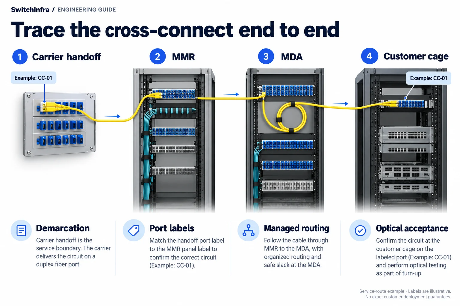
Trace each cross-connect from the carrier handoff through the MMR and MDA to the customer cage, preserving labels and acceptance records. Conceptual illustration; equipment shapes are illustrative.
Third-party project account · Independent analysis by SwitchInfra
Not a SwitchInfra deployment. Candidate equipment is proposed for comparable requirements.
20+ locations — operator scope reported
8 markets — North American footprint reported
MMR → MDA — reported carrier handoff route
Customer cage — reported service destination
What the documented project tells us
Corning describes an unnamed multitenant operator whose carrier meet-me room connects through a main distribution area to customer cages. Excess jumper length and difficult connection identification motivated a distribution-management change.
This account makes service demarcation the central engineering problem. Improving the frame layout should make a connection easier to identify, change and hand over; it does not remove the need to verify the optical service carried through it.
Operator — The supplier reports more than 20 locations across eight markets.
Path — Carrier handoffs pass through an MDA to customer cages.
Problem — Long and disorganized jumpers complicated moves and changes.
Management — The solution uses managed routing and in-bay jumper storage.
Scope of the analysis: Public project analysis of a third-party supplier account. Not a SwitchInfra deployment or independent acceptance report. Every proposed rate and model below is a separate design exercise.
Work through the engineering choices
Start with the documented constraint, then state the conditions for the proposed equipment role.
Identify the service boundary at each end
The reported route has distinct carrier, distribution and customer handoffs.
Design exercise: Design exercise: specify one new customer cross-connect.
Record the carrier port or panel, operator distribution positions and the exact customer handoff. Identify who owns each jumper, termination and active optical interface. A cage label or order number alone is not a complete service endpoint.
Include the service rate, media grade, connector and polish at the handoffs. State whether the order covers only passive fiber or also active equipment. This prevents an optical-module quotation from silently including work outside the agreed demarcation, or a passive handover from being mistaken for a tested application service.
Standardize routing without concealing spare length
The source describes routing management and in-bay storage.
Design exercise: Design exercise: review a standard jumper length for a distribution bay.
Trace the intended route through vertical and horizontal management, including storage and access for adjacent services. Confirm the assembly’s bend and handling requirements. A uniform jumper can simplify inventory, but only if the available route stores its extra length predictably without obstructing maintenance.
Specify a labeling and change record that follows both jumper ends. Keep physical route identifiers stable when customer names change. Before a move, confirm the affected service and its rollback path; physical neatness alone does not prove that a technician has identified the correct connection.
CommScope cassette and distribution reference
Review active optics against the complete passive route
The case does not disclose link rates or optical PIDs.
Design exercise: Conditional examples: 10G or 100G services on verified single-mode channels.
SFP-10G-LR, QSFP-100G-CWDM4-S and QSFP-100G-LR4-S serve different port and reach requirements. Evaluate them only after the customer and carrier endpoints are known. An operator’s dense distribution frame does not establish that either active endpoint supports those PIDs.
Include all agreed cross-connects, adapters and intermediate assemblies in the loss budget. Verify host software and, where applicable, FEC at both ends. A longer-reach optic is not an automatic cure for poorly documented patching, and the nominal reach is not a service-level commitment.
Cisco 10G optical module data sheet · Cisco 100G optical module data sheet · Cisco optics compatibility matrix
Make the handover useful for the next change
Request a service record that another technician can follow without reconstructing the installation. Pair the passive-channel result with whatever active testing the agreed scope requires, and distinguish those two forms of evidence.
Cisco optics compatibility matrix
Demarcation
Carrier and customer handoffs, ownership and passive versus active scope.
Route
Frame positions, jumper lengths, storage arrangement and stable identifiers.
Service
Host configurations, optical budget, acceptance results and change responsibility.
Candidate models and selection boundaries
These are illustrative model inquiries, not the equipment installed in the source project. Confirm the required rate and complete channel before finalizing any line.
| Model / family and status | Role and condition |
|---|---|
| SFP-10G-LR Conditional model inquiry | Independent 10G SMF service example Requires suitable carrier/customer hosts and a verified channel. Cisco 10G optical module data sheet |
| QSFP-100G-CWDM4-S Conditional model inquiry | Independent 100G SMF service example Assess both hosts, FEC and all cross-connect losses. Cisco 100G optical module data sheet |
| QSFP-100G-LR4-S Conditional model inquiry | Alternative 100G SMF reach option Not a blanket replacement for channel remediation. Cisco 100G optical module data sheet |
Listed models are independent design candidates, not equipment identified in this project. IDs are supplied only for previously verified exact catalog matches. Other PIDs are model inquiries; supply and platform compatibility are unconfirmed.
Continue in the relevant product family
Use the analysis to define the role before comparing catalog options.
Discuss this project
Carry the route, media, endpoint and loss requirements into the inquiry. Leave unknown quantities blank; source-project fiber counts are not an equipment BOM.
Follow the next selection question.
Compare related decisions while keeping each source’s scope, hardware and link conditions separate.
Browse more engineering analyses →
Single-mode university data center: 100G / 40G selection
A G.657.A2 fiber plant makes the complete optical channel central to the equipment choice.
Read the engineering analysis · Original project account
Expand mixed OM4 and single-mode cabling
A public Xi’an expansion account becomes a practical guide to channel allocation, 1U fiber density and patching-loss budgets.
Read the engineering analysis · Original project account
Building interconnect: pretermination or splicing?
Compare complete installation, mapping and acceptance packages at high fiber counts.
Read the engineering analysis · Original project account
Before you finalize the channel
Does a passive cross-connect prove the customer service works?
No. Passive-channel acceptance and active service testing have different scopes and should be recorded separately.
Should every jumper be cut to the shortest possible length?
Use lengths compatible with the frame’s intended routing, storage and maintenance access. Excess length must have an explicit management path.
Does Corning identify the operator or its installed optics?
The operator is anonymized and active optical models are undisclosed. Do not infer a customer identity.
What should a cross-connect RFQ contain?
Specify both demarcations, service ownership, media, connector finish, route and loss information, endpoint configurations and the required handover scope.
Trace the project facts and technical limits
- Corning project account
- CommScope cassette and distribution reference
- Cisco 10G optical module data sheet
- Cisco 100G optical module data sheet
- Cisco optics compatibility matrix
Source check: 19 October 2026. Catalog status is stated per candidate.
Sources checked 19 October 2026. Publication date, customer identity and installed optics remain undisclosed. No savings or reliability claim is treated as an independent acceptance result.