
Cisco · power-stack
Campus Stack Resilience: Separate Data Paths from Power Sharing
Design and test data stacking and power sharing independently, with exact accessories and a documented failure-state power budget.
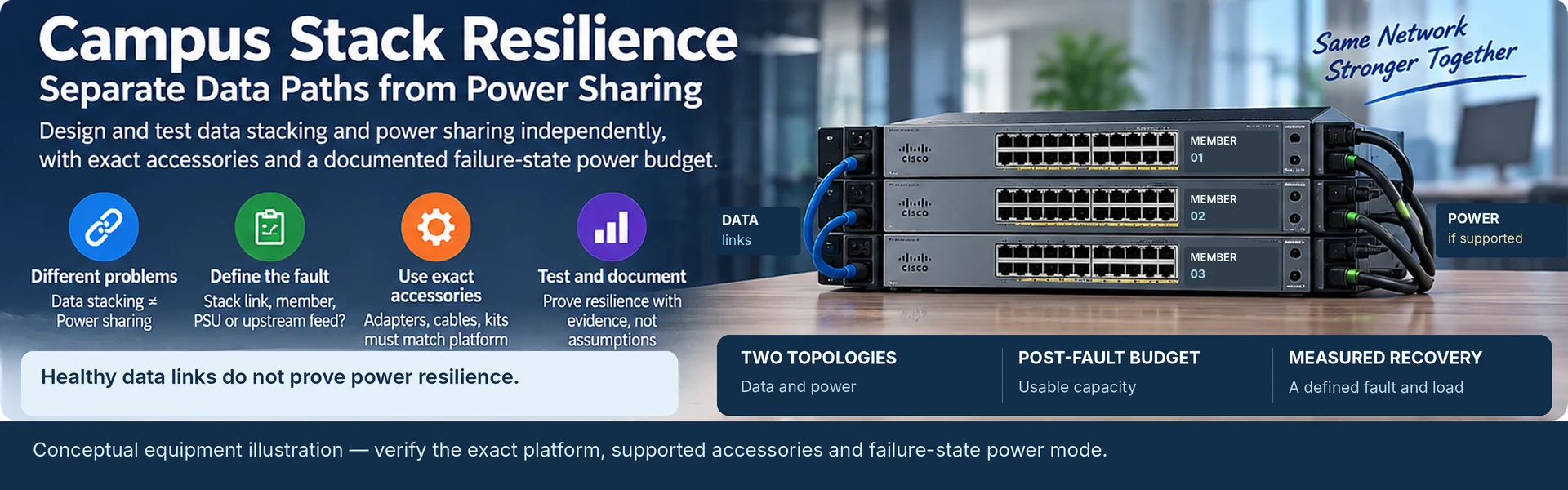
A campus switch stack can have healthy data links while its power-resilience objective remains unmet. Data stacking and power sharing solve different problems and need separate drawings, accessory lists and acceptance tests.
Start by naming the fault the access block must tolerate. “Redundant stack” is incomplete unless it states whether the design protects against a stack-link failure, a member failure, a power-supply failure or an upstream electrical-feed failure.
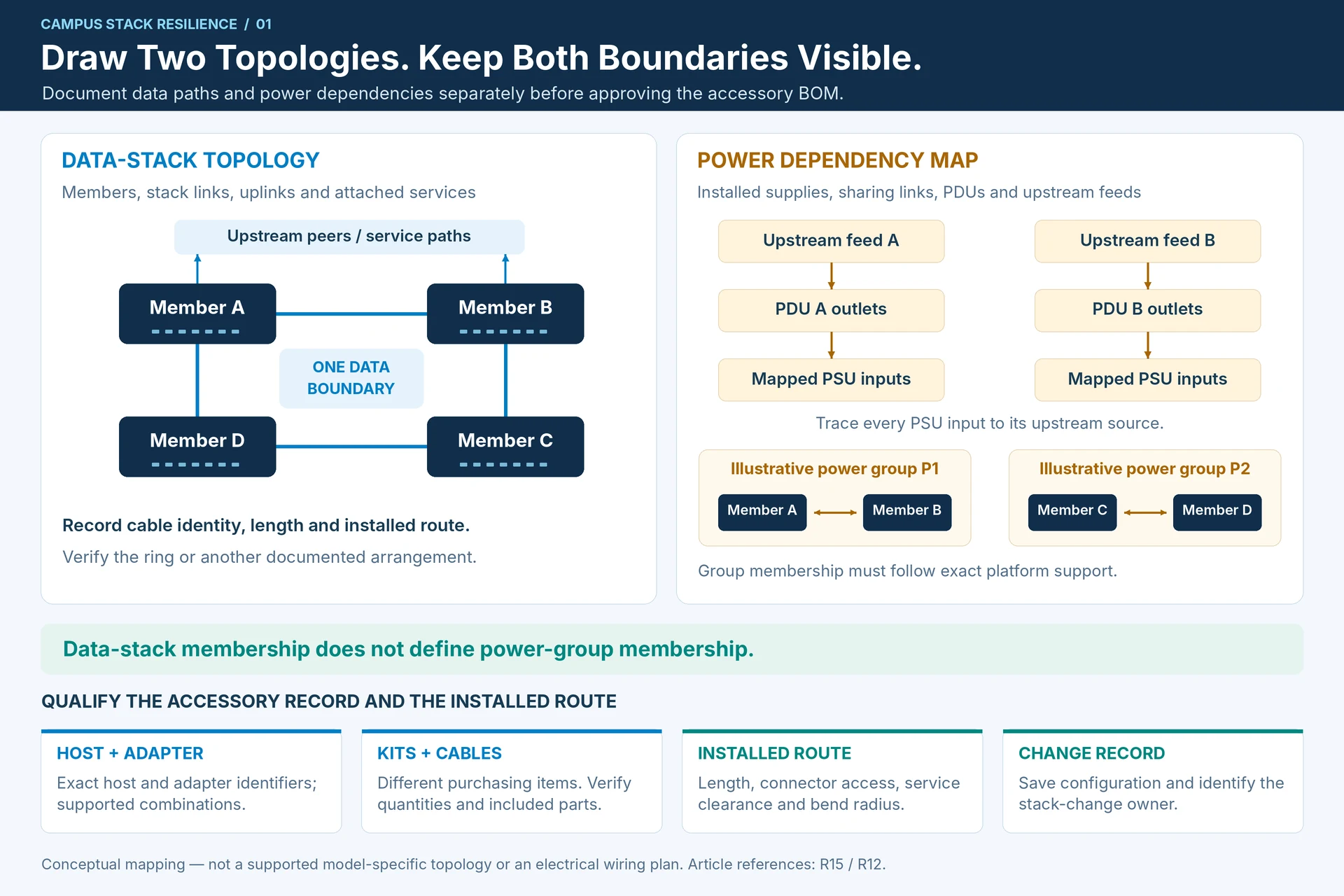
Draw two topologies
The data drawing should show stack members, supported stack adapters, cable identities, lengths and the intended ring or other documented arrangement. Add uplinks and identify the services attached to each member.
The power drawing should show installed supplies, power-sharing connections where supported, PDU outlets and upstream feeds. Cisco’s Catalyst documentation distinguishes StackWise and StackPower functions and platform-specific installation requirements. One should not be inferred from the presence of the other. R15R12
An access block may share a data-stack boundary but use a different power-group boundary. Keep both visible in the design record.
Budget the power available after a fault
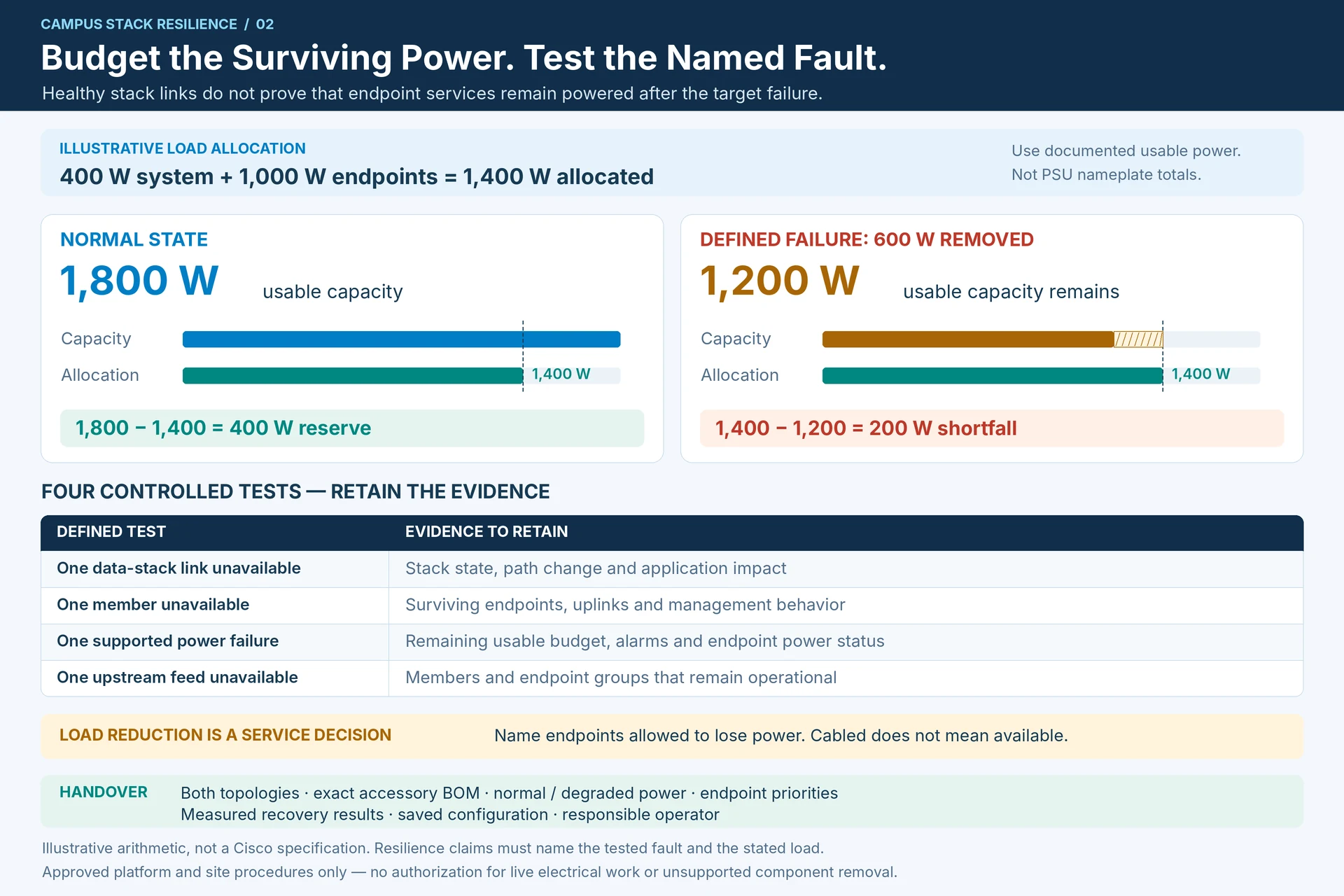
As a simplified planning illustration, suppose a supported arrangement has 1,800 W of usable capacity for the loads being considered, with 400 W allocated to switch-system demand and 1,000 W to endpoints. The normal reserve is 400 W. If a defined failure removes 600 W of usable capacity, only 1,200 W remains against a 1,400 W allocation: a 200 W shortfall.
This is a load-balance example, not a specification or supported topology for any Cisco model. Replace the figures with the system’s documented usable power, configured operating mode and actual allocation. Do not substitute PSU nameplate totals for the available PoE budget.
Where the design permits priority-based load reduction, document which endpoints may lose power. A camera, phone or access point that remains cabled but unpowered is not an available service.
Match accessories to the exact platform
A stacking adapter, an adapter kit and a cable are different purchasing items. Confirm quantities and included parts. Preserve host and accessory identifiers, since similarly named Catalyst variants can use different combinations.
Measure the installed route, allowing for connector access and a supported bend radius. A cable that reaches only when pulled tightly may prevent service access or strain the connector. Do not force a convenient ring drawing onto an impractical rack layout.
Use a failure matrix
| Controlled test | Evidence to retain |
|---|---|
| One data-stack link removed | Stack state, path change and application impact |
| One member unavailable | Surviving endpoints, uplinks and management behavior |
| One supported power failure | Remaining budget, alarms and endpoint power status |
| One upstream feed unavailable | Which members and endpoint groups remain operational |
Perform tests only under the approved platform and site procedure. A conceptual resilience plan does not authorize live electrical work or an unsupported component removal.
Deliver a maintainable access block
Include both topologies, exact accessory BOM, normal and degraded power calculations, endpoint priorities and measured recovery results. Save the configuration and identify the operator responsible for future stack membership changes.
The final claim should match the evidence: for example, tolerance of one specified stack-link failure under a stated load. That is more useful than calling the entire installation “fully redundant” without defining its limits.
Engineering illustrations
These figures illustrate the design concepts discussed here. They are not measured results, certified configurations or a supplied-equipment list.
Related reading
- Cisco Power and Stack Accessories: Build Two Separate Compatibility Records
- StackWise and StackPower Protect Different Parts of the Network