
Cisco · voice
Voice Gateway Migration: Analog Roles, Digital Trunks and Cutover Tests
Plan a voice-gateway migration by mapping carrier and endpoint roles, selecting compatible modules and validating complete call flows.
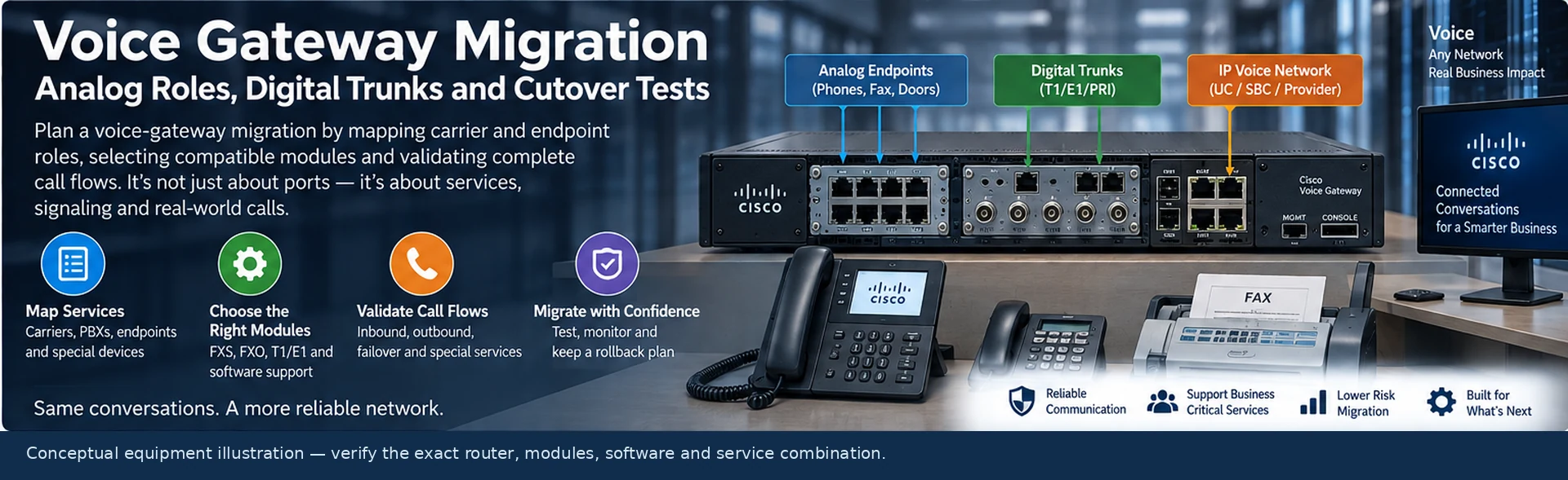
A voice-gateway migration can fail even when every network interface is up. The replacement may present the wrong analog role, use the wrong digital signaling configuration or omit resources needed by the intended call flow. Start with services and signaling, then choose the router and modules.
This solution is intended for a controlled replacement or expansion of an existing voice environment. It is not a recommendation to substitute one module solely because its connector looks similar.
Inventory services, not just ports
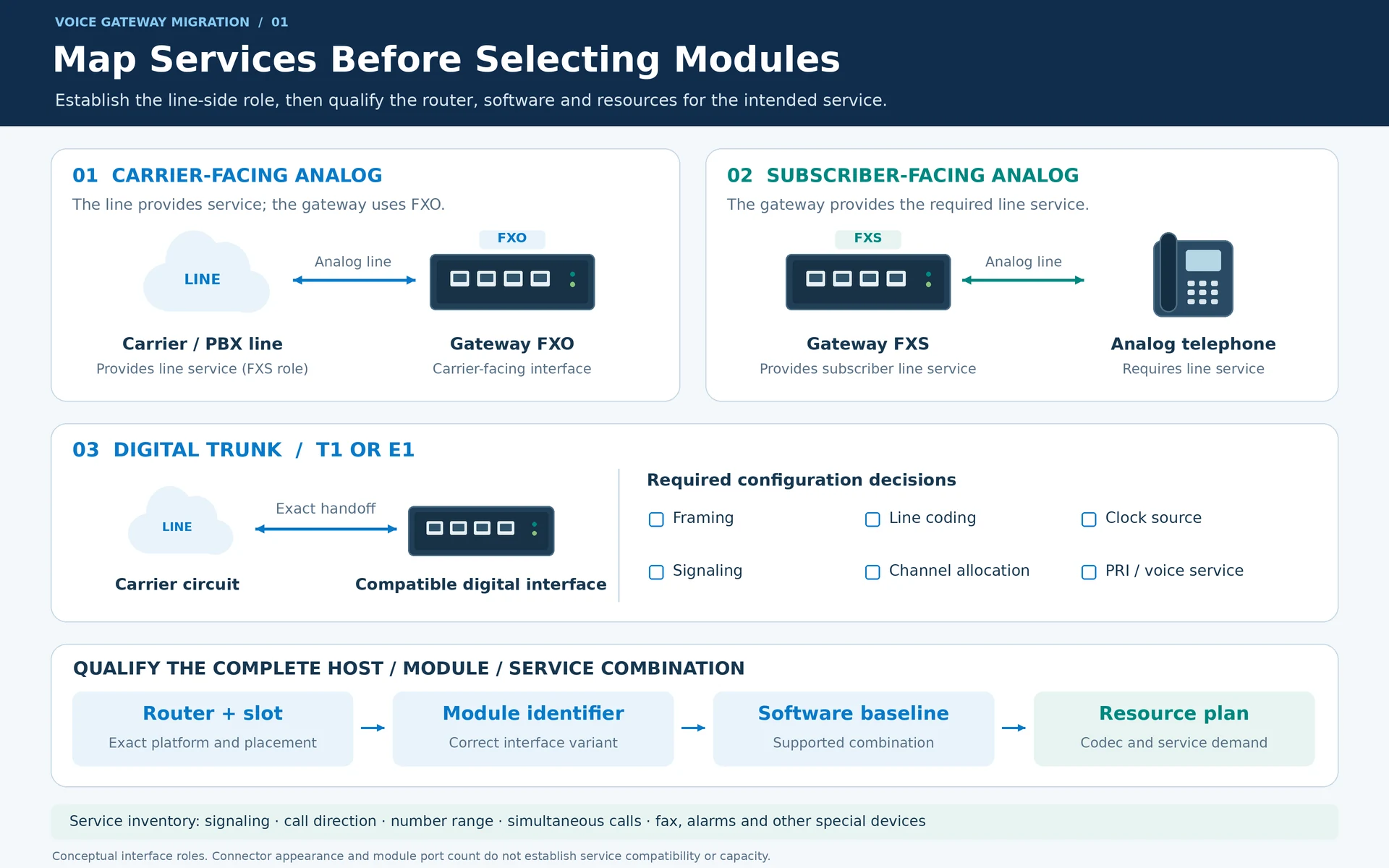
Create one record per carrier circuit, PBX connection or endpoint group. Include the current interface, signaling method, call direction, number range, simultaneous-call requirement and the application that depends on it. Identify fax, alarm, door-entry and other special-purpose devices separately from ordinary handsets.
An analog subscriber-side connection and an analog trunk-side connection have different electrical and signaling roles. Cisco’s FXS/FXO documentation is the starting point for establishing those roles. A gateway FXO interface normally faces an FXS-providing line; a subscriber device requiring line service needs the appropriate FXS-providing interface. R22
Match the host, module and service
For digital circuits, confirm whether the handoff is T1 or E1 and identify framing, line coding, clock source and signaling. A physical T1/E1 interface does not, by itself, establish that the intended PRI or voice service is configured. Cisco’s NIM documentation treats these as explicit configuration decisions. R21
Check the exact router model, slot, module identifier and supported software combination. Then calculate resources for the actual codec, transcoding, conferencing or other services that the deployment will use. Module port count alone is not a capacity model for every voice function.
| Connection | Questions the design must answer |
|---|---|
| Analog carrier line | Which side supplies line service, and how are calls detected and disconnected? |
| Analog endpoint | Which port provides the required subscriber-side function? |
| Digital trunk | Which framing, clocking, signaling and channel allocation apply? |
| IP call-control path | Which systems own routing, authentication, media and failover? |
Draw both signaling and media paths
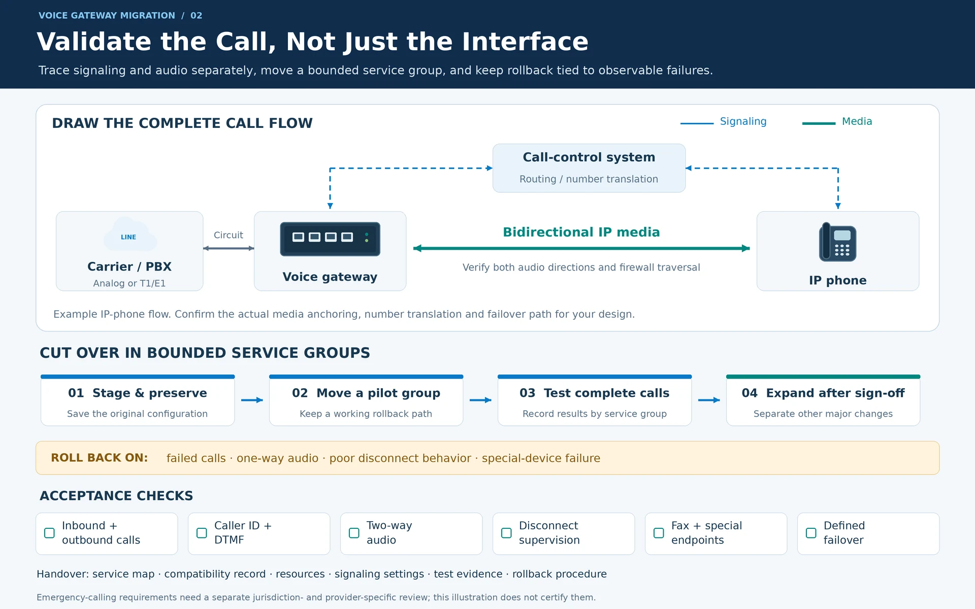
Trace an inbound call from the carrier to the destination and an outbound call in the reverse direction. Include number translation, dial-plan decisions, firewall traversal and the media path. A signaling session that succeeds does not prove that audio flows in both directions.
Define the intended behavior when a WAN link or call-control component fails. Do not describe a fallback as available until a representative call has been tested through it.
Cut over in service groups
Stage the router and modules, retain the original configuration and prepare test numbers. Move a bounded set of services first. Keep rollback criteria tied to observable failures such as failed call completion, one-way audio, unacceptable disconnect behavior or a special-purpose endpoint that cannot operate correctly.
Avoid combining an interface migration, a complete dial-plan redesign and a carrier change in one untested step. Separating those changes makes fault isolation and reversal more practical.
Accept the complete call flow
Test inbound and outbound calls, caller identification where required, DTMF, disconnect supervision and the specific fax or other services in scope. Validate the defined failover path and retain results by service group. Emergency-calling obligations require a separate jurisdiction- and provider-specific review; this network plan does not certify them.
The handover should include the service map, module/host compatibility record, resource plan, signaling settings, test evidence and rollback procedure. These records turn a collection of voice interfaces into a maintainable service.
Engineering illustrations
These figures illustrate the design concepts discussed here. They are not measured results, certified configurations or a supplied-equipment list.
Related reading
- Voice Interface Selection: FXO, FXS, T1/E1 and PRI Requirements
- FXO and FXS: Match the Telephone-Line Role Before the Module