
Network engineering
Data Center Cabling Solutions: Choose a Channel Architecture That Can Grow
Compare direct-attach, structured fiber and modular cabling approaches by route, optical interface, serviceability and expansion needs.
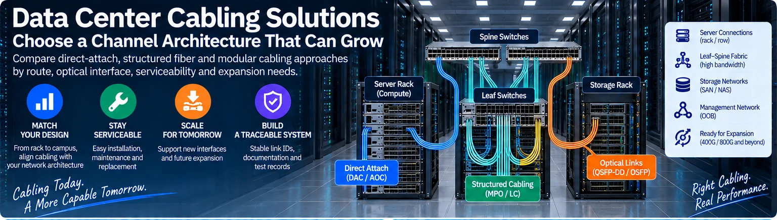
Data center cabling connects the network design to the physical room. A useful architecture must accommodate current interfaces, predictable expansion and the way technicians replace equipment. The goal is not maximum connector density in isolation; it is a set of qualified, traceable channels that remain serviceable as the fabric changes.
Start with the route and the operating model
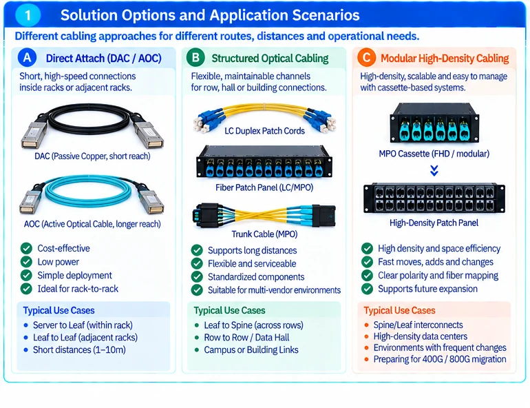
Map server-to-leaf, leaf-to-spine, storage and management connections separately. Record whether links stay inside a rack, cross a row or pass through a central distribution area. These routes determine where fixed assemblies are practical and where structured patching may improve maintenance.
Also identify the expected change pattern. A stable rack with short fixed links presents a different service problem from a shared facility where equipment moves frequently.
Select the relevant solution path
| Project need | Planning focus |
|---|---|
| Short high-speed connections | Exact DAC/AOC support, routed length and replacement access |
| Structured optical channels | Fiber, optical interface, channel loss and intermediate connections |
| Modular high-density patching | Cassette compatibility, polarity, fiber mapping and physical service space |
| Reliable moves and changes | Stable link IDs, patch schedules and change control |
| Future fabric expansion | Reserved paths, termination capacity and explicit interface assumptions |
Use the detailed high-speed-cabling, fiber-cabling, modular-MTP and cable-management articles for those respective tasks. They address different layers of the same infrastructure rather than interchangeable product categories.
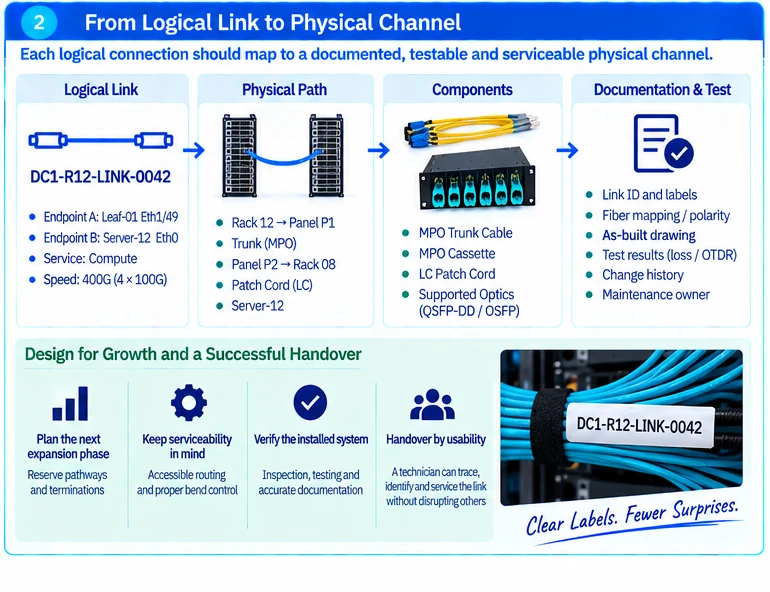
Keep logical links separate from physical components
One physical cage or multi-fiber connector may support more than one logical connection, depending on the implementation. Conversely, one logical link may cross several physical segments. NVIDIA’s documented twin-port arrangements illustrate why component counts cannot be inferred from a speed label alone. R01
For each channel, retain the endpoint ports, active components, cable or fiber segments, patch positions and operating mode. For parallel optics, document which fibers carry each channel. Multi-fiber connector guidance reinforces the importance of polarity and mapping. R42
Reserve capacity with a purpose
Specify the next growth step: additional racks, more server links or a changed optical interface. Then reserve the corresponding pathway, termination and fiber resources. A generic statement that the cabling supports “future 800G” is too broad without an interface and channel assumption.
A reusable fiber route may still need different terminations, optics or channel qualification when the interface changes. Modularity makes changes manageable; it does not make all components interoperable.
Accept the installed system
Require as-built drawings, labels and test results that resolve to individual links. Inspect optical connections appropriately and verify the complete channel against the selected application. Connector inspection alone is not a channel-loss or reach test. R17
For project scoping, provide the rack layout, endpoint inventory, target interfaces, route distances and expected expansion. Those inputs allow the cabling architecture to support both the current fabric and a clearly defined next phase.
Engineering illustrations
These figures illustrate the design concepts discussed here. They are not measured results, certified configurations or a supplied-equipment list.
Related reading
- Data Center Cable Management: Build a Traceable, Serviceable Link System
- Modular MTP Cabling with FHD Components: Mapping, Loss and Expansion
- Data Center Fiber Cabling: Engineer and Test the Complete Optical Channel