
Network engineering
Deploying a 400G Interconnect: Staging, Cutover and Acceptance
Turn an approved 400G interconnect design into a controlled deployment with baseline records, staged tests and rollback triggers.
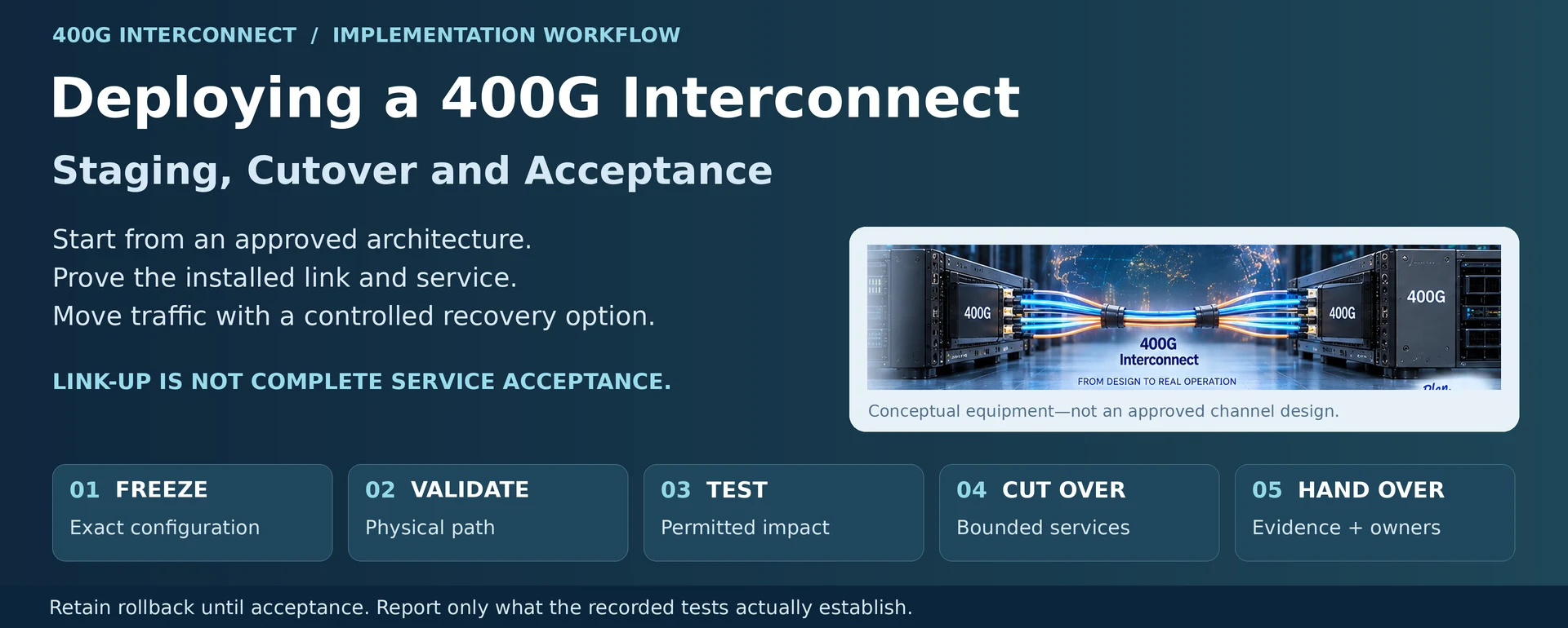
A 400G interconnect deployment should begin with an approved architecture, not with an attempt to discover the design during the maintenance window. The implementation task is to prove that the installed components and service behave as specified, then move production traffic with a controlled recovery option.
Gate 1: Freeze the deployable configuration
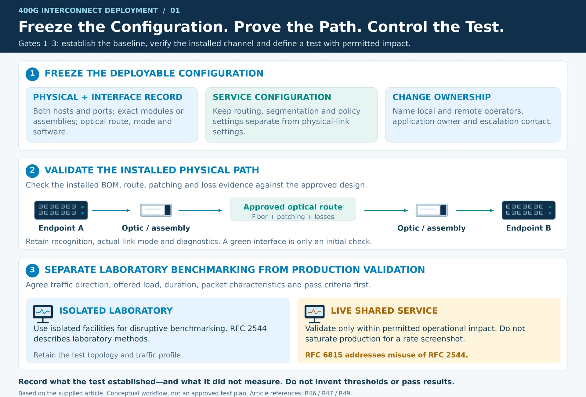
Record both endpoint devices and ports, modules or assemblies, optical route, target operating mode and software versions. Confirm the support evidence for the exact combination. Retain interface settings and the intended service configuration separately so that a physical-link fault can be distinguished from a routing or policy fault. R49
Create a change record naming the local operator, remote operator, application owner and escalation contact. Define what each party must observe during cutover.
Gate 2: Validate the physical path
Check inventory and installation against the approved BOM. Inspect the optical channel, verify any supplied loss results and confirm that the route and patching match the drawing. Establish the link with the required mode and record diagnostics where available.
A green interface state proves only that a limited set of link conditions has been met. It does not prove acceptable error behavior, forwarding performance or application reachability.
| Acceptance layer | Evidence to retain |
|---|---|
| Physical | Installed identifiers, channel record, link mode and diagnostics |
| Forwarding | Test topology, traffic profile, packet sizes and error/loss observations |
| Service | Routing, segmentation and intended application paths |
| Resilience | Triggered fault, interruption observed and recovery action |
| Operations | Monitoring visibility, alarms and recoverable management access |
Gate 3: Test without confusing the laboratory and production
Agree on traffic direction, offered load, duration, packet characteristics and pass criteria before the test. Use isolated test facilities for disruptive benchmarking. RFC 2544 defines laboratory benchmarking methods; RFC 6815 specifically addresses the risks of applying those tests to production networks. R46R47
A production validation should be designed around the permitted operational impact. Do not saturate a live shared service simply to produce a “400G tested” screenshot. Record what the test actually established and what it did not measure.
Gate 4: Move a bounded service set
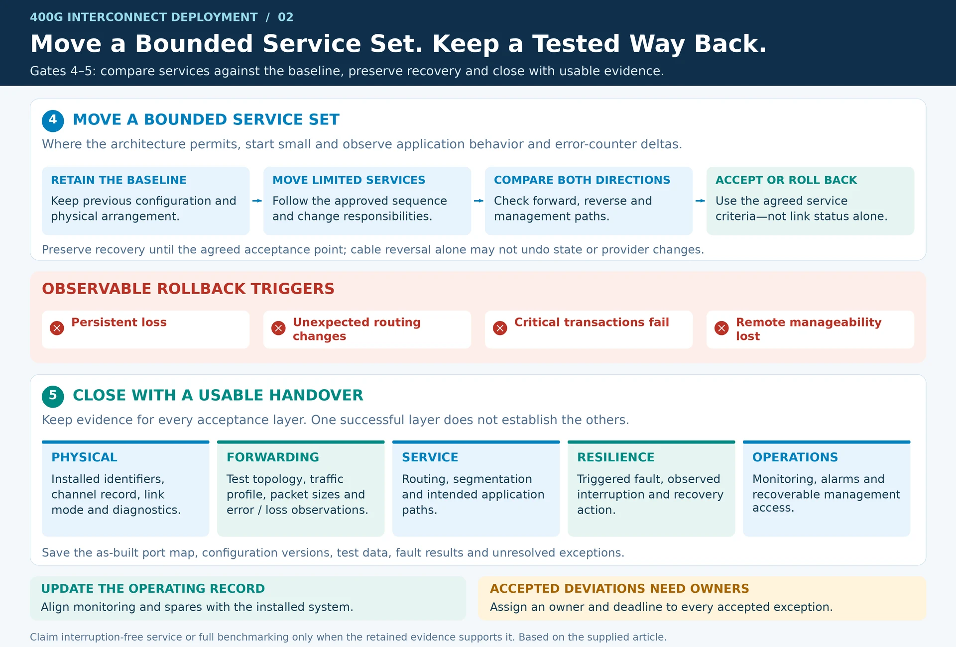
Where architecture permits, migrate a limited set of services first. Compare application behavior and error-counter deltas against the baseline. Check reverse traffic and management paths as well as the obvious forward path.
Set rollback triggers such as persistent loss, unexpected routing changes, failure of critical application transactions or loss of remote manageability. Preserve the previous configuration and physical arrangement until the agreed acceptance point. A cable reversal alone may not undo stateful or provider-side changes.
Gate 5: Close with a usable handover
Save the as-built port map, configuration versions, test data, fault results and unresolved exceptions. Update monitoring and spare records to match what was actually installed. Assign an owner and deadline to any accepted deviation.
The final result is a documented service transition. It should not be described as interruption-free or fully benchmarked unless the retained evidence supports those specific claims.
Engineering illustrations
These figures illustrate the design concepts discussed here. They are not measured results, certified configurations or a supplied-equipment list.
Related reading
- 400G Cloud Interconnect Architecture: Define the Service Before the Optic
- 400G Data Center Design Guide: Ports, Capacity, Optics and Acceptance
- SFP+, QSFP28 and QSFP-DD Selection: Form Factor Is Only the First Filter