
Network engineering
Enterprise Cabling Solutions: Connect Work Areas, Buildings and Growth Plans
Organize enterprise cabling into horizontal, building-backbone and interbuilding systems with clear qualification and handover requirements.
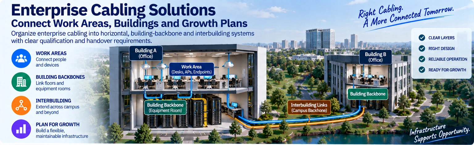
Enterprise cabling should be planned as connected layers with different responsibilities. Work-area connections, building backbones and interbuilding routes do not face the same distance, service or maintenance constraints. Separating those layers makes it easier to choose the correct design and avoid solving every problem with a new switch.
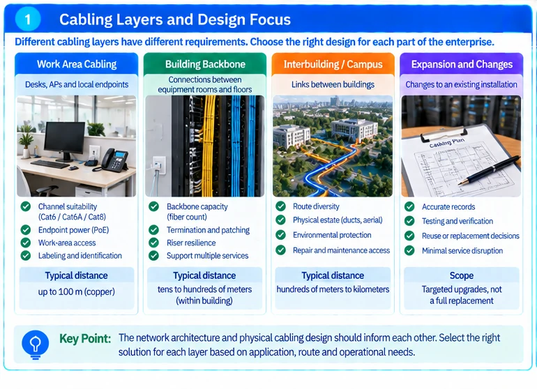
Choose the layer that matches the project
| Project scope | Main design task | Detailed solution |
|---|---|---|
| Desks, APs and local endpoints | Channel suitability, endpoint power and work-area access | Horizontal cabling |
| Connections between equipment rooms and floors | Backbone capacity, termination and riser resilience | Building backbone |
| Links between buildings | Route diversity, physical estate and repair access | Campus infrastructure |
| Changes to an existing installation | Accurate records, testing and reuse decisions | Channel review and remediation |
The network architecture and physical cabling design should inform each other. Campus design guidance can help identify service boundaries, but it does not replace a site-specific pathway and installation review. R45
Define the application rather than buying a label
Record intended endpoint interfaces, required traffic behavior and any power delivered over copper. For fiber, identify the optical interface and complete channel arrangement. A cable category or fiber color alone does not establish that the installed path meets the application.
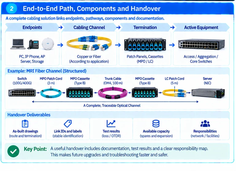
Where multi-fiber components are proposed, document mapping and polarity. A modular panel can organize several links without converting their optical standards. R42
Separate installation scope from network scope
Agree who supplies active devices, optics, patch leads, permanent cabling, panels and test records. Also identify responsibility for building access, pathway protection and applicable safety requirements. Ambiguous scope can leave a technically suitable design incomplete at handover.
An illustrative project might retain existing horizontal channels, replace a congested backbone and add a diverse interbuilding path. That targeted scope is more defensible than replacing every cable solely because the access switches are being refreshed.
Make reuse an evidence-based decision
Collect existing route and test records, inspect terminations and qualify the completed channel for the intended application. Replace components when the evidence shows that they cannot meet the requirement or cannot be maintained acceptably. Avoid assuming either that all existing cabling is unusable or that an old passing result qualifies a new interface.
Inspection and cleaning address connector condition; additional channel tests may be needed to establish loss and application suitability. R17
Require a maintainable handover
The minimum useful output is an as-built route and termination record, stable labels, test results and a list of available capacity. Each record should resolve to a physical channel and its supported use.
For initial planning, provide floor and building layouts, endpoint counts, current cabling records and the expected growth step. The resulting solution can then focus on the layer that limits the project rather than prescribing unnecessary changes across the entire estate.
Engineering illustrations
These figures illustrate the design concepts discussed here. They are not measured results, certified configurations or a supplied-equipment list.
Related reading
- Building Backbone Cabling: Capacity, Route Resilience and Service Access
- Campus Fiber Infrastructure: Design Between Buildings, Not Just Between Ports
- Horizontal Cabling for Enterprise Endpoints: Data, Power and Maintainability