
Network engineering
Enterprise WLAN Design: Capacity, Coverage and Client Experience
Plan enterprise wireless around real client behavior, RF conditions, wired dependencies and measurable service acceptance.
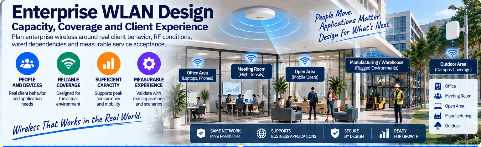
A wireless network is successful when its clients can use the required applications in the places and conditions that matter. Signal coverage is necessary, but it does not establish capacity, roaming quality or application continuity. Begin with the client population and the physical environment rather than an access-point count.
Describe where and how clients work
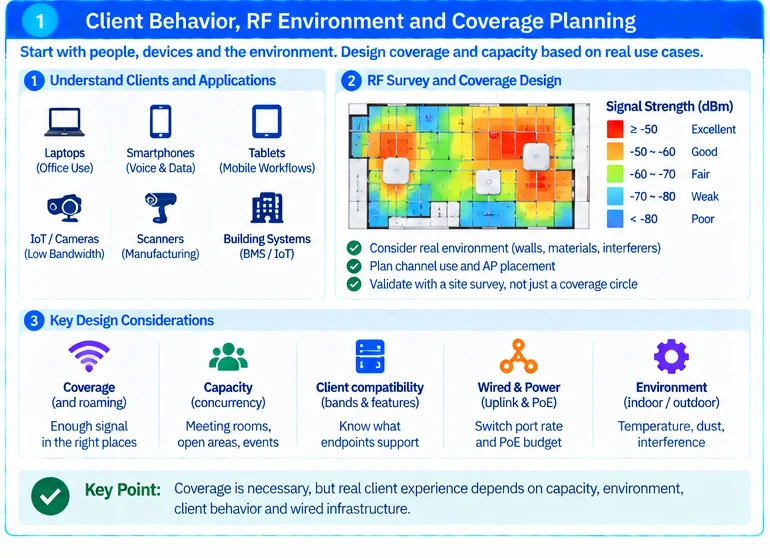
Record occupied areas, client types, expected concurrency and application requirements. Distinguish stationary office use from voice calls, meeting-room bursts and mobile workflows. Include the clients’ supported bands and capabilities; an AP feature has limited value when the endpoint cannot use it.
Site surveys should consider the actual environment and intended service. Cisco’s survey guidance treats planning and validation as an engineering process, not a coverage circle drawn around each AP. R37
Evaluate four connected layers
| Layer | Design responsibility |
|---|---|
| Radio environment | Coverage, interference, channel use and AP placement |
| Client behavior | Association, authentication, roaming and application needs |
| Wired access | Ethernet rate, PoE availability and uplink capacity |
| Service infrastructure | Addressing, name resolution, identity and policy enforcement |
A faster AP uplink does not fix an RF problem. Likewise, a good radio design can be undermined by insufficient power or an overloaded wired path. Verify the endpoint’s documented power mode and the switch’s available budget rather than assuming every powered AP operates with its full feature set. R32
Choose a deployment pattern that the team can operate
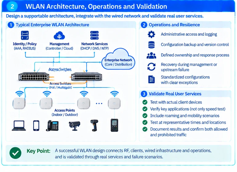
Define management and controller dependencies, configuration ownership and recovery behavior. Decide which services continue during an upstream or management-system failure, and test those assumptions. Campus design guidance can help connect WLAN architecture to the wired network, but the site-specific failure objectives remain essential. R45
For a small office, unnecessary architectural complexity may add more maintenance burden than value. For a large campus, consistency and controlled change become more important than manually tuning every AP independently.
Validate at representative times and locations
Test actual client devices in occupied areas, including movement paths where roaming matters. Observe the chosen application metric, not only a speed-test result. Record RF conditions, client model, software and concurrency so that results remain interpretable.
An illustrative acceptance plan could include a meeting room under realistic attendance, a mobile voice path and a business application used at the coverage edge. These scenarios are project-specific, not universal signal or throughput thresholds.
Use the small-office and manufacturing-wireless solutions for their distinct operational contexts. For an initial WLAN design, provide floor plans, building materials, client inventory, application requirements and current survey findings. These inputs support a measurable client experience rather than a promise based on nominal radio rates.
Engineering illustrations
These figures illustrate the design concepts discussed here. They are not measured results, certified configurations or a supplied-equipment list.
Related reading
- Small-Office Wi-Fi: Reliable Coverage with a Supportable Wired Foundation
- Manufacturing WLAN: Design for Mobile Workflows and Production Constraints
- C9300X Multigigabit Selection: Verify the Port Mix and PoE Budget