
AI & HPC networks
Can a twin-port 400G optical assembly serve four 200G endpoints?
Check lane generation, shared split mode and complete PMD before ordering fiber fanout.
A passive splitter can expose lanes in a supported parallel optical design, but it cannot make arbitrary 200G equipment compatible. The correct purchasing decision joins the electrical port mode, optical engine and fiber mapping as one channel specification.
The short answer
Use only a documented endpoint combination. In the described twin-port arrangement, select either two straight 400G paths or four 200G split paths, with consistent mode across the two optical ports. Match PMD, media, connectors and host support.
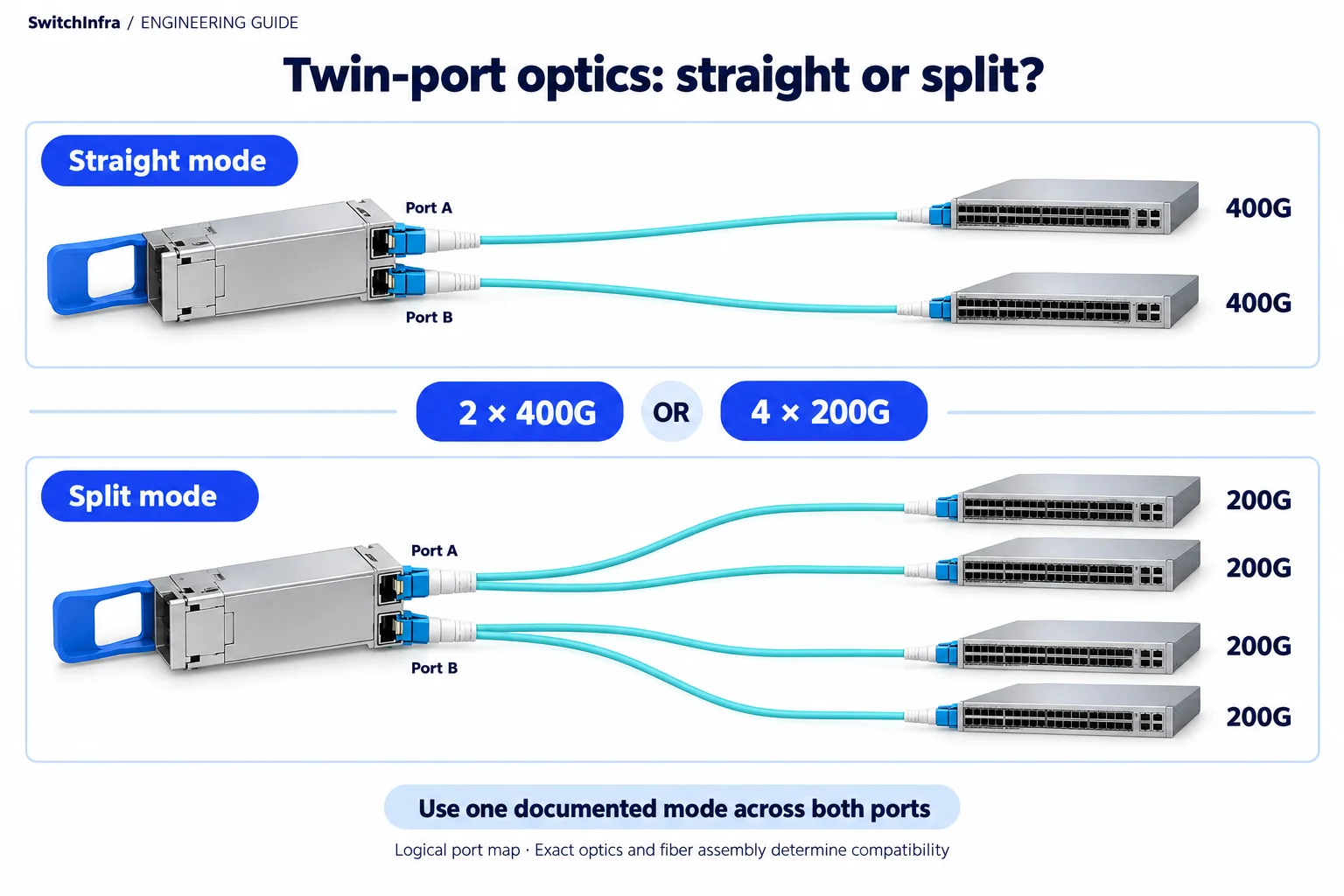
For the documented twin-port arrangement, use the supported mode consistently across both ports: two 400G links or four 200G links. Conceptual illustration; equipment shapes are illustrative.
Official technical sources · Independent analysis by SwitchInfra
This is a documented design analysis, not a customer deployment claim. Candidate roles require verification for your configuration.
2 × 400G — straight-path arrangement
4 × 200G — documented split arrangement
100G-PAM4 — documented lane technology
PMD-specific — fiber mapping and reach
What the technical reference establishes
NVIDIA’s LinkX documentation describes twin-port optical assemblies that connect to two 400G endpoints or four 200G endpoints through the corresponding fiber arrangement. It also specifies a shared straight-versus-split mode across the twin ports.
This is a channel-selection problem, distinct from counting a switch’s logical ports. Begin with the exact endpoint generation and requested service, then determine whether the proposed optics expose compatible lanes at both ends.
LinkX 100G-PAM4 optics and fiber details
Mode — The documented twin-port arrangement uses consistent straight or split paths.
Parallel channel — DR4 uses a parallel optical lane arrangement.
Connector — The documented parallel family uses MPO-12/APC.
Different PMD — The 2×FR4 long-reach role uses duplex LC interfaces.
Scope of the analysis: Independent selection analysis of official NVIDIA documentation. Proposed examples are not a deployed customer project or a SwitchInfra delivery.
Work through the engineering choices
Start with the documented constraint, then state the conditions for the proposed equipment role.
Freeze the endpoint generation and lane requirement
The reference arrangement is based on 100G-PAM4 lanes.
Design exercise: Proposed task: qualify four intended 200G endpoints individually.
Do not infer compatibility from the number 200G alone. Identify the remote adapter OPN, protocol and supported lane mode, then request the documented pairing for the selected switch and optics. Equipment using a different electrical or optical arrangement may require a different interconnect solution.
Describe each child path explicitly in the RFQ. A branch should identify its parent optical port, endpoint and required rate. Confirm software and FEC behavior with the supported combination. If the endpoint cannot operate in that arrangement, exclude the proposed split design rather than promising that a cable will translate it.
LinkX 100G-PAM4 optics and fiber details · LinkX 100G-PAM4 product overview
LinkX single-port DR4 QSFP112 family
Adapter or DPU endpoint inquiry
Match PMD, lane mapping, cage support and exact reach.
Choose one supported operating mode for the shared assembly
The documented twin ports cannot mix straight and split fiber arrangements.
Design exercise: plan four 200G children across two splitter paths.
Keep all four endpoint records tied to the parent assembly. Assess whether future changes require regrouping ports or replacing the fiber arrangement. A shared operating constraint means a seemingly small endpoint upgrade may affect a neighboring service that uses the same module housing.
Write the required switch mode and complete splitter mapping into the delivery schedule. Validate all branches together under traffic and preserve their observed peers. Testing only one child link leaves the remaining mapping, mode and service behavior unproven, even when the parent module appears healthy.
LinkX 100G-PAM4 optics and fiber details
LinkX twin-port 2×DR4 OSFP family
Two 400G or qualified split links
Select exact reach and switch-end heat-sink form; model inquiry.
MPO-12/APC splitter assembly family
Conditional four-200G channel map
Use the documented matching split mode; not an arbitrary passive speed converter.
Keep parallel DR4 and wavelength-multiplexed FR4 designs separate
The product overview distinguishes parallel MPO and long-reach LC interfaces.
Design exercise: Proposed task: select one complete PMD and channel design for each link role.
Trace the chosen fiber through all patching and verify media, polarity, connector finish and measured loss. An MPO connector name does not establish the correct lane map, while an LC channel does not expose parallel lanes for a DR4 splitter. Keep reach tied to the exact optical parts.
The documented 2×FR4 family is a separate long-reach inquiry, not an interchangeable four-branch solution. Request the exact end-to-end pairing, module power, cage support and routed length before accepting either option.
LinkX 100G-PAM4 product overview · LinkX 100G-PAM4 optics and fiber details
LinkX 2×FR4 twin-port OSFP family
Separate long-reach switch-link inquiry
Duplex-LC wavelength-multiplexed role; do not apply the DR4 splitter design.
Make every branch a reviewable channel
Quote the switch assembly, remote modules and fiber topology together. Include shared operating constraints so later changes cannot silently invalidate another endpoint on the same parent.
LinkX 100G-PAM4 optics and fiber details
Endpoints
Exact devices, protocols, electrical lanes, operating mode and software.
Optics
Matching PMD, cage form, power, reach and supported pairing.
Fiber
Media, finish, polarity, split mapping, loss and per-branch test evidence.
Candidate models and selection boundaries
These are conditional model or product-family inquiries for the documented equipment roles. Confirm the required rate and complete channel before finalizing any line.
| Model / family and status | Role and condition |
|---|---|
| LinkX twin-port 2×DR4 OSFP family Conditional model / family inquiry | Two 400G or qualified split links Select exact reach and switch-end heat-sink form; model inquiry. LinkX 100G-PAM4 optics and fiber details |
| LinkX single-port DR4 QSFP112 family Conditional model / family inquiry | Adapter or DPU endpoint inquiry Match PMD, lane mapping, cage support and exact reach. LinkX 100G-PAM4 optics and fiber details |
| MPO-12/APC splitter assembly family Conditional model / family inquiry | Conditional four-200G channel map Use the documented matching split mode; not an arbitrary passive speed converter. LinkX 100G-PAM4 optics and fiber details |
| LinkX 2×FR4 twin-port OSFP family Conditional model / family inquiry | Separate long-reach switch-link inquiry Duplex-LC wavelength-multiplexed role; do not apply the DR4 splitter design. LinkX 100G-PAM4 optics and fiber details |
Official model or family references only. Exact SwitchInfra listings, offered configuration, supply and project compatibility have not been verified; request confirmation by model.
Continue in the relevant product family
Use the analysis to define the role before comparing catalog options.
For the separate 100G SR4, 400G SR4 and MPO cable decisions, use the LinkX optics and cabling selection guide. These are different channel designs; a catalog link does not establish a compatible pairing.
Discuss this project
Carry the route, media, endpoint and loss requirements into the inquiry. Leave unknown quantities blank; reference port and fiber counts are not an equipment BOM.
Follow the next selection question.
Compare related decisions while keeping each source’s scope, hardware and link conditions separate.
Browse more engineering analyses →
ConnectX-7: a 400G upgrade starts inside the server
Qualify the host slot, exact connector and current feature support before buying interconnects.
Read the engineering analysisOfficial technical source
H100 SuperPOD: four fabrics, four connection schedules
Keep compute, storage, service access and OOB management distinct before counting equipment.
Read the engineering analysisOfficial technical source
HGX Spectrum-X: separate SuperNIC and DPU duties
Keep GPU communication, converged services and management distinct in the node and fabric BOM.
Read the engineering analysisOfficial technical source
Before you finalize the channel
Does any 200G endpoint work behind this splitter?
No. The exact generation, lane mode and documented pairing must match.
Can one twin port use straight fiber and the other split?
The described arrangement requires a consistent mode across both.
Can LC FR4 replace a parallel DR4 splitter path?
Do not infer that. Their optical channel structures differ.
Are the family references orderable exact SKUs?
No. Select and confirm exact model variants, supply and support first.
Trace the project facts and technical limits
Source check: 19 October 2026. Catalog status is stated per candidate.
Official sources read 19 October 2026. Project-specific engineering review, firmware support, exact offered parts and supply remain unconfirmed.