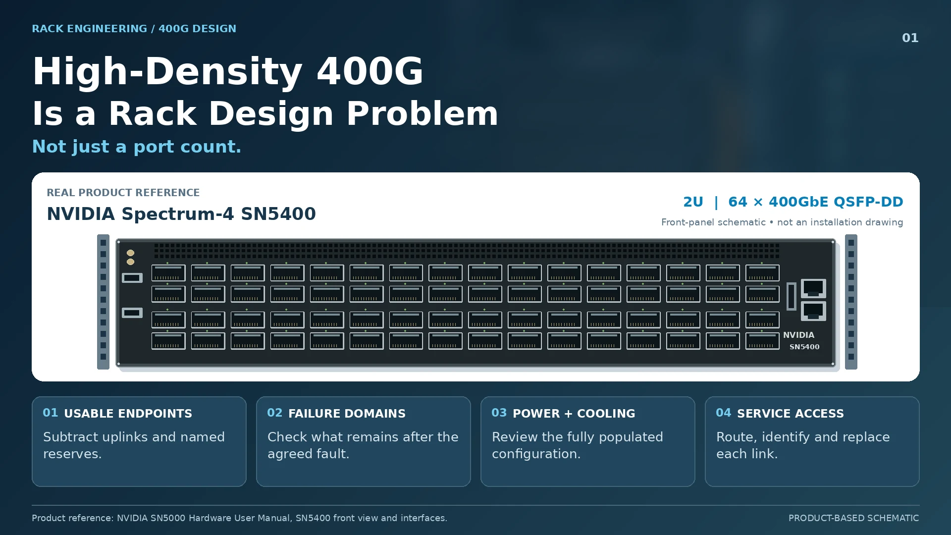
Ports per rack unit is an appealing comparison because it is simple. Unfortunately, it describes only the faceplate. A dense 400G deployment also concentrates power, optical modules, cables and maintenance activity.
The useful metric is not maximum connector count. It is the capacity that remains usable within the rack’s installation, resilience and operating constraints.
Count ports after the architecture has used its share
A switch’s interfaces may be divided among endpoints, uplinks and reserved growth. Those allocations change how many useful connections the rack actually provides.
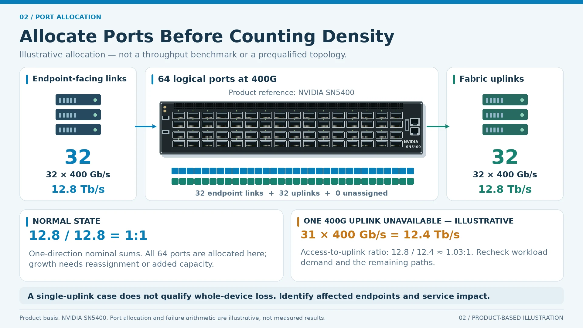
For an illustrative, model-independent 64-logical-port design, assigning 32 ports to endpoints and 32 to fabric uplinks produces 32 endpoint connections—not 64. At 400Gb/s each, both groups sum to 12.8Tb/s of nominal one-direction capacity. This is arithmetic for a planning example, not proof that a particular device is nonblocking under every traffic pattern.
The architecture must also state the surviving capacity after a defined failure. A compact system can place more endpoints inside the same failure boundary.
Optics and cooling belong in the first layout
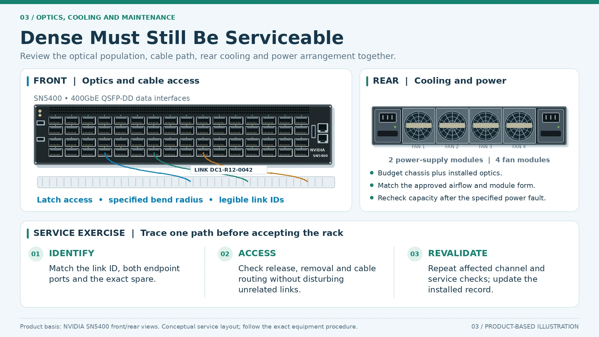
The installed optical configuration affects power and thermal planning. Modules with similar external forms can have different cooling requirements; NVIDIA’s interconnect documentation provides concrete examples of host-specific thermal arrangements. R01
Use the actual proposed module population and equipment documentation when reviewing rack conditions. Do not estimate a fully populated optical system from a chassis-only power figure or assume that all airflow variants are equivalent.
Cable density can reduce serviceability
A technically valid connection still needs a route that allows installation and replacement. Plan management trays, bend radius, slack, labels and access to adjacent modules. Consider what a technician must disconnect to replace one failed component.
An illustrative service exercise is to trace and remove one planned optical path using the rack drawing. If that operation requires disturbing a large bundle of unrelated links, the layout may be dense in a way that increases operational risk.
| Density measure | What the faceplate count omits |
|---|---|
| Usable endpoint density | Ports consumed by uplinks and reserves |
| Surviving density | Capacity after the agreed fault |
| Thermal density | Chassis plus installed optical configuration |
| Operational density | Cable access, labeling and replacement work |
Make the comparison at the service boundary
Compare architectures with the same endpoint and failure requirements. Include rack space, power, interconnects and operating effort. A larger enclosure can be appropriate if it produces a more maintainable system; a denser one can be appropriate when its constraints are understood and supported.
Validate the resulting design with a test method that matches the intended claim. Device-level benchmarking and application acceptance answer different questions; a port-rate sum is neither of them. R46
The best high-density design leaves no ambiguity about where its ports go, how its optics are cooled or how a failed link is replaced. That is what turns a compact faceplate into useful 400G infrastructure.
Engineering illustrations
These figures illustrate the design concepts discussed here. They are not measured results, certified configurations or a supplied-equipment list.