
InfiniBand · XDR
XDR 800G Fabric Planning: Port Architecture and Migration Boundaries
Plan an XDR deployment from exact switch architecture, endpoint modes, cooling and interconnect requirements before migrating production racks.
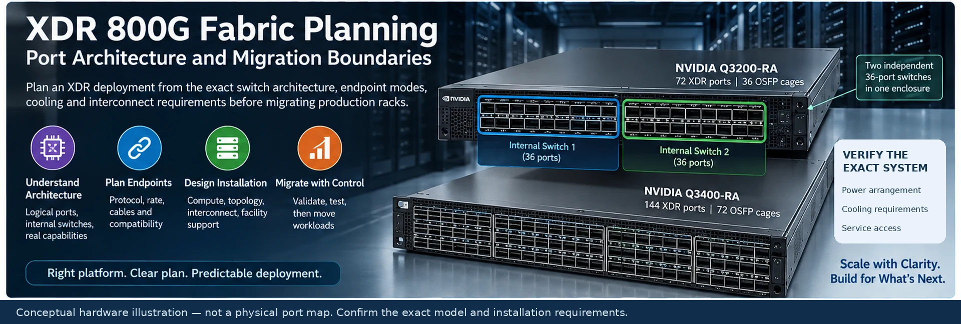
Moving to XDR is a platform and topology decision, not simply a change from a “400G” label to an “800G” label. The design must identify the logical switching architecture, supported endpoint modes, physical interconnects and installation requirements of the exact system being purchased.
This planning framework separates a new XDR domain from equipment that will remain in service. It avoids treating every Q3-family system or every high-capacity OSFP module as interchangeable.
Read the switch architecture before counting ports
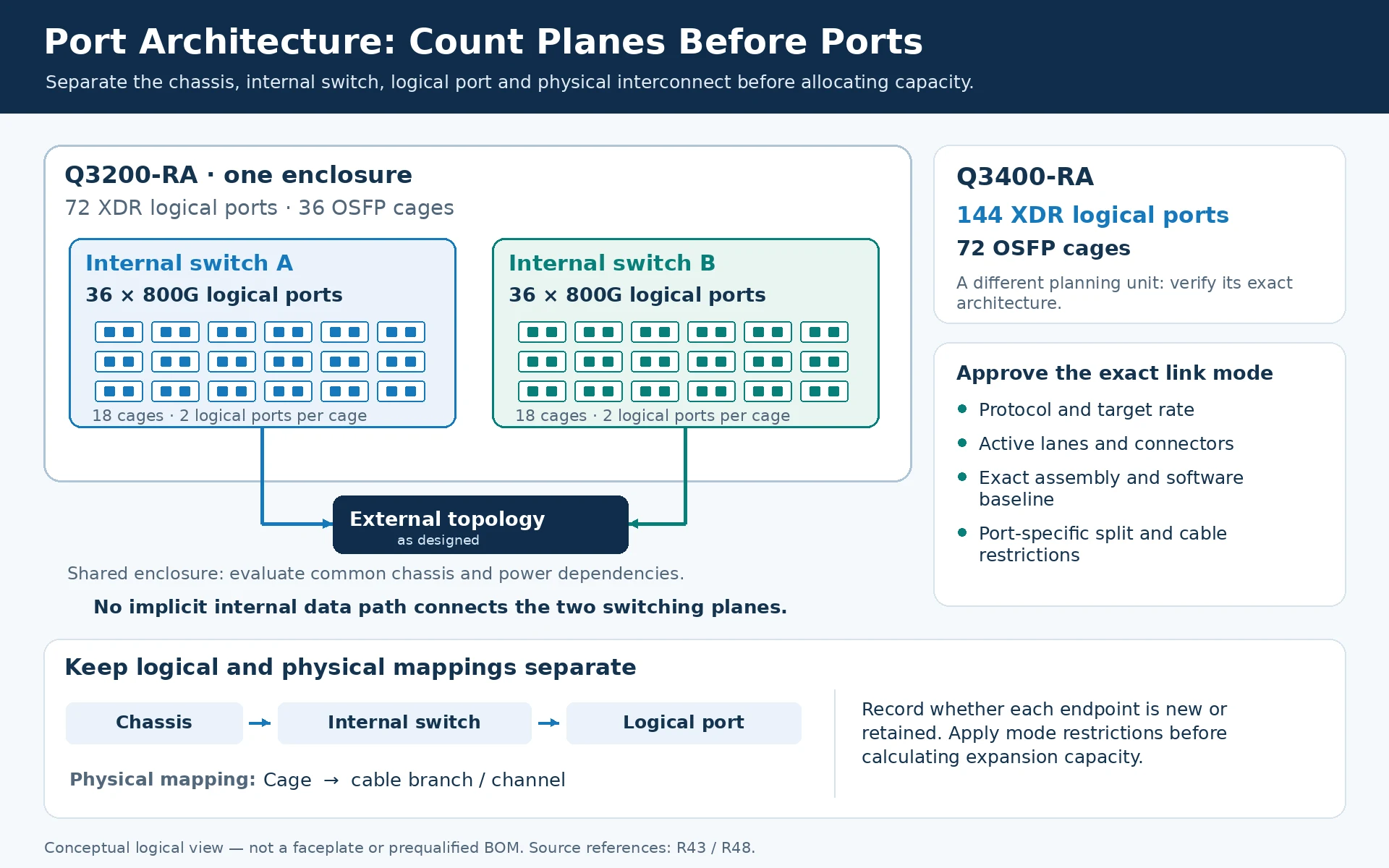
NVIDIA documents Q3200-RA as 72 XDR ports across 36 OSFP cages, implemented as two independent 36-port switches in one enclosure. Its Q3400-RA documentation lists 144 XDR ports across 72 OSFP cages. Those layouts are not interchangeable planning units. R43R48
For a Q3200-based design, draw the two internal switches separately. An endpoint attached to one is not automatically on the same internal switching plane as an endpoint attached to the other. Account for the external topology that connects the intended domains.
A useful drawing therefore needs three identifiers: chassis, internal switch where applicable, and logical port. Cages and cable branches are a second mapping layer.
Build a mode-by-mode endpoint matrix
For every proposed link, record protocol, target rate, active lane arrangement, host connector, switch port and exact cable or optical assembly. Identify whether the endpoint is new or retained, and which firmware and driver baseline is required.
A mixed-generation connection should be approved at the actual operating mode rather than by the highest speed printed on either device. NVIDIA’s Q3200 design guidance also documents port-specific split-mode and cable restrictions. Apply those restrictions to the port map before calculating expansion capacity. R48
Separate four installation designs
| Workstream | What must be resolved before procurement |
|---|---|
| Compute attachment | Server slot and adapter readiness, protocol and rail mapping |
| Fabric topology | Independent switching planes, host/uplink allocation and failure behavior |
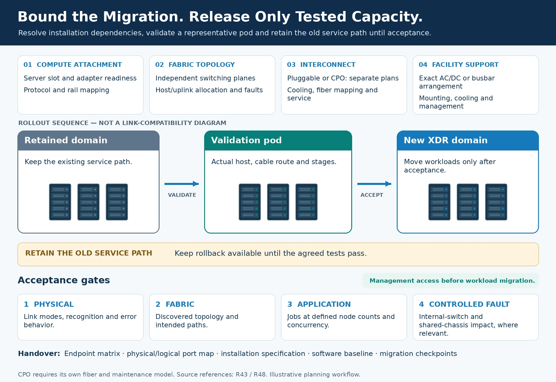
| Interconnect | Pluggable or CPO implementation, module cooling, fiber mapping and serviceability |
| Facility support | Exact AC/DC or busbar arrangement, mounting, cooling and management access |
Do not derive the power or cooling specification from a similar model name. The XDR manual distinguishes systems with different management, power-supply and physical-interface arrangements. R43
For a pluggable design, count modules and channels according to the supported connector implementation. A CPO-based system requires its own fiber and maintenance model; it should not inherit a conventional “two transceivers per link” worksheet.
Choose a bounded migration strategy
A clean new domain simplifies version control but requires an explicit plan for service movement. A mixed-generation domain may reuse infrastructure, but every reused path adds a compatibility and operating-mode dependency.
Start with a representative validation pod containing the host type, cable route and switching stages used in the larger design. Establish management access before moving workloads. Retain the old service path until the new domain has passed the agreed physical, fabric and application tests.
Release capacity only after acceptance
Measure representative jobs at defined node counts and concurrency. Test the failure domain described in the design, including the consequences of losing an internal switch or shared chassis where relevant. A shared enclosure can create dependencies that are invisible in a logical port total.
The deployment record should include the endpoint matrix, physical/logical port map, installation specification, validated software baseline and migration checkpoints. That is the appropriate basis for an XDR quotation and rollout plan—not an aggregate module-rate comparison.
Engineering illustrations
These figures illustrate the design concepts discussed here. They are not measured results, certified configurations or a supplied-equipment list.
Related reading
- ConnectX and BlueField Selection: Host Fit, Protocol and Offload Requirements
- Optics and Cable Selection Checklist: Qualify Both Endpoints and the Channel
- What “800G” Really Describes: Port Rate, Module Capacity and Compatibility