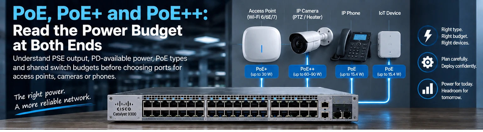
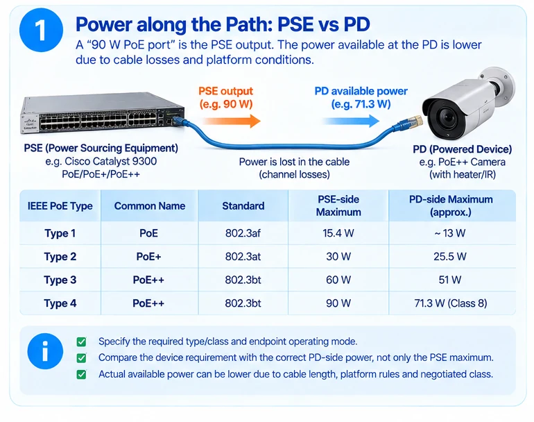
A “90 W PoE port” does not mean every connected device receives 90 W. It describes a power capability at a particular boundary, subject to the supported type, classification, channel and platform conditions.
The most important distinction is between the power-sourcing equipment (PSE)—typically the switch—and the powered device (PD), such as an access point or camera.
The cable is part of the power path
The PSE must account for power lost in the channel. Consequently, the power available at the PD is lower than the PSE-side maximum. HPE Aruba Networking’s PoE documentation distinguishes these boundaries and the associated types and classes. R32
The following summarizes commonly referenced maximum boundaries, not a guarantee for every port, cable or endpoint:
| IEEE PoE type | Common naming | PSE-side maximum | PD-side maximum or approximate boundary |
|---|---|---|---|
| Type 1 | PoE, associated with 802.3af | 15.4 W | About 13 W |
| Type 2 | PoE+, associated with 802.3at | 30 W | 25.5 W |
| Type 3 | Often grouped under PoE++, 802.3bt | 60 W | 51 W |
| Type 4 | Often grouped under PoE++, 802.3bt | 90 W | 71.3 W for Class 8 |
“PoE++” alone is not sufficiently precise for an equipment schedule. Specify the required type/class, endpoint operating mode and actual supported platform. Lower classes and negotiated allocations can be below the table’s type maxima. R32
A powered device may have more than one operating mode
Consult the endpoint documentation for the functions that must be active. Successful boot does not establish that every radio, heater, camera function or accessory is operating as intended.
Compare the device’s requirement with power available at the correct boundary. Do not compare a PD requirement directly with an equal PSE maximum and assume the channel losses have disappeared.
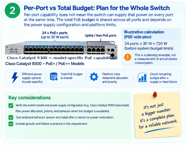
The switch budget is shared
Per-port capability and total available PoE capacity are different specifications. The installed power-supply arrangement and platform rules determine what can be allocated across the switch. Cisco’s Catalyst documentation provides model-specific power options rather than one universal family budget. R12
For an illustrative PSE-side plan, 24 ports allocated 30 W each require 720 W before any separate system-budget considerations imposed by the platform. That is not a measurement of actual device consumption and not proof that a 24-port PoE+ switch can provide it.
Record how the switch reserves or negotiates power and how priorities behave when available capacity changes.
Failure behavior belongs in the requirement
Decide which devices must remain operational after a supply or feed failure. Check the remaining budget, not only the normal total. Test endpoint behavior after reboot or restoration where those events are part of the acceptance scope.
The data path needs a separate check. A device can remain powered without providing its required network service, and a healthy uplink cannot prevent a device from rebooting when power is removed.
A complete PoE enquiry therefore includes endpoint models, quantities, desired operating modes, channel conditions, power priorities and the required failure state. Those details are more useful than asking for the largest wattage number on a product page.
Engineering illustrations
These figures illustrate the design concepts discussed here. They are not measured results, certified configurations or a supplied-equipment list.
Related reading
- Faster Ethernet Does Not Mean More PoE: Plan Data and Power Separately
- C9300X Multigigabit Selection: Verify the Port Mix and PoE Budget
- Long-Reach PoE Design: Separate the Data Path from the Power Problem